Last updated on the 16/02/2015 23:37
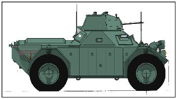
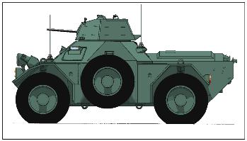
Common markings found on a Daimler Ferret and where to look.
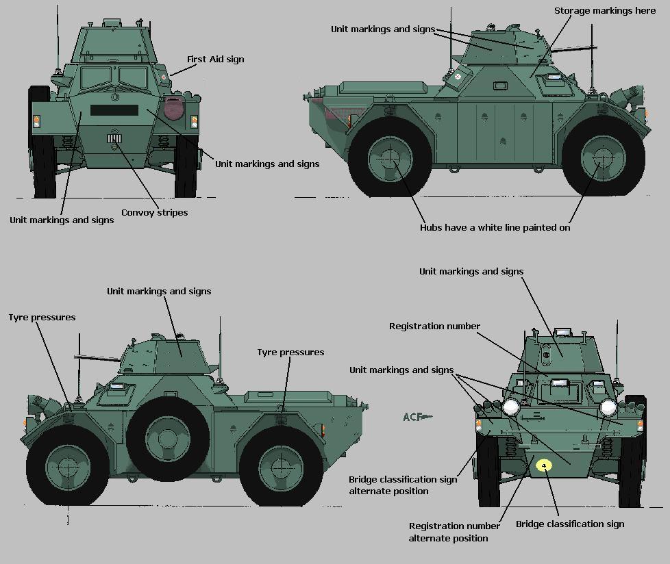
What do you do now that you have found the Army Registration markings on you're Ferret?
Contact the Tank Museum at Bovington and for a small fee of about £15 they will send any information that they hold on you're vehicle. www.tankmuseum.co.uk
Electrical conduit renewal
Pictures and description courtesy of Diana and Jackie
The Electrical conduit on our Ferret is in a poor state. Numerous layers of paint and worse still rotten because the galvanised conduit under the braid was totally rusted.
Here's how to renew the conduit. Bear in mind the conduits can be a different size. This exercise was to renew the conduit on the headlamps and side/turn indicators on a Ferret
Tools - Heat Gun, adjustable tube / pipe cutter, pipe wrench, screwdrivers, junior hacksaw, vice.
Stores :-Brass tube 9/16 x .014 (eBay),
Sleeving Braid MBS 95-7.5mm 10M Reel (rapidonline). Part No. 03 -1913
Metal conduit sleeving, nickel plate on brass - 10mm bore (vintagecarparts). Part No. 763
Electrical cored solder.
Screw on ferrules (pack of 6 on eBay, military surplus).
Note - do not use plumbing flux, if the brass parts are cleaned properly the solder wil flow with very little problem. Galvanised steel flexible conduit can be used but in time it will rust again, it will also cause a problem in soldering, the flexible metal conduit sleeving of brass will take solder easily.
The original screw fitting will most likely be of brass, if the fittings are under the mudguards or body re-use brass, if they are on the top surface of the vehicle then new screw fittings maybe used.
Take care not to damage the brass end fittings inside the old conduit. I have been unable to source new ones. There is no reason why with care they cannot be re-used, along with the screw fittings.
Next the photos:-..........
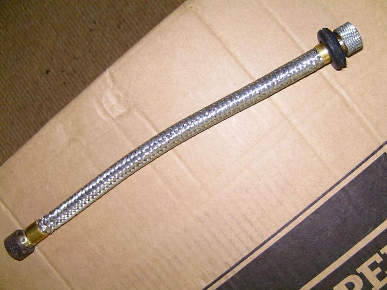
A finished example as a taster....
Remove the old conduit, take care not to damage the wiring, it is preferable to disconnect the wiring, pull it through the old conduit and then remove the conduit. Mark the wiring as necessary.
If the conduit goes through the wings or body of the vehicle cut through the conduit as most likely it will pass through a rubber grommet.
Grommets can be removed and reused if necessary and it is a lot easier to remove them without the conduit in the way. The Grommets on our vehicle were probably 50 years old and in good condition.
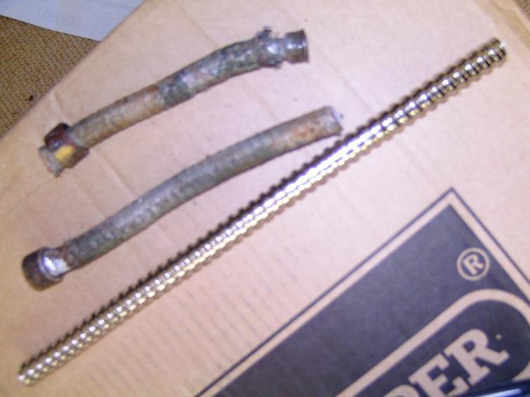
Here is a picture of the old conduit cut in half. The Grommet it passed through was saved. We need to keep the end fittings.
This is the new conduit, cut ready to length using the old conduit as a guide. A junior hacksaw will cut the conduit, better still an abrasive cutting disc for a cleaner cut.
The next stage is to unsolder the end fittings. The Ferrules which fit over the braid are not going to be reused. On the first conduit we did the end fittings dropped out easily after we applied heat. On the second headlamp conduit the brass ferrule had to be cut off before the end fittings would drop out as we unsoldered it.
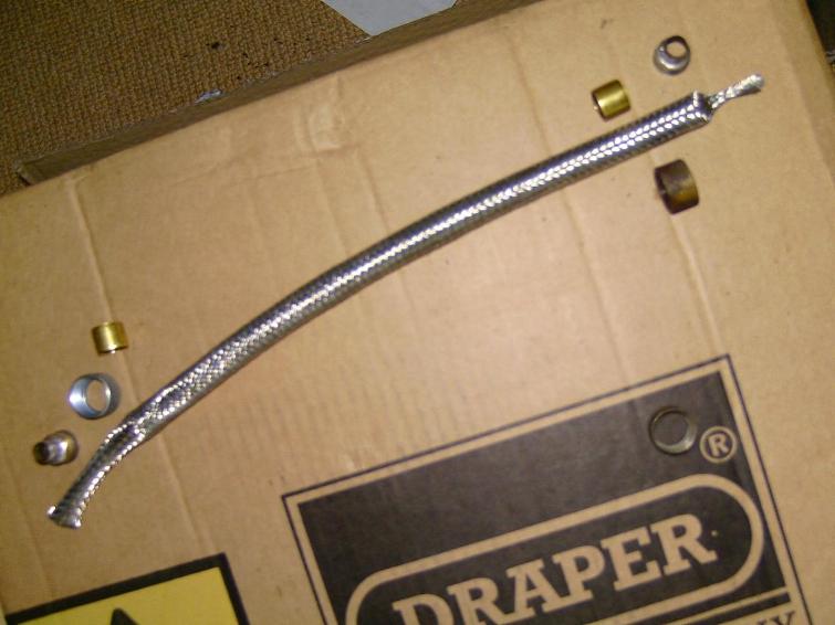
Here you can see the roll of braid, new ferrules, a new and old screw fitting and the fittings which are soldered inside the flexible conduit.
Here the braid is slid over the new conduit. Make sure the braid is longer (about 30mm at least) than the conduit underneath. Cut the brass tube which will become the ferrule over the braid, with a tube cutter.
Use the length of the old ferrule to determine the length of the new ferrule. Tube cutters often close up the ends of tube. Make sure that the end of the ferrule is not reduced in diameter, if it is use a rat tail file to open it up.
Clean up all parts to be soldered. Kitchen scourers work wonders! If the flexible conduit is new and clean inside very little cleaning will be necessary. Do not attempt to clean the braid unless it is dirty / corroded.
Slide the new brass ferrule over the braid and conduit, the reason for leaving extra braid will now become apparent, as it makes it easier to slide the ferrule, ensure that the end of the ferrule and the end of the new conduit are flush.
Cut the excess braid, a sharp kitchen scissors is good, trim it back as close to the end of the conduit as possible. Stray ends can be tucked down inside the conduit, slide the recovered end fitting inside the conduit and tight against the ferrule.
Warm the end assembly and flow ample solder into the joint between the ferrule and end fitting. Capillary action will cause the solder to flow inside the assembly.
NOW THE IMPORTANT BIT.... FIT both screw fittings onto the new assembly, ensure that they face the correct way - screw ends out. If any grommets need to be fitted now is the time to do it.
Repeat the process of fitting the ferrule and end fitting on the remaining end. Make sure the braid is tight over the length of the flexible conduit before finally completing the soldering on the last end.
A neat job can be done of soldered joints by wiping with a damp cloth or towel roll, take care not to burn yourself.
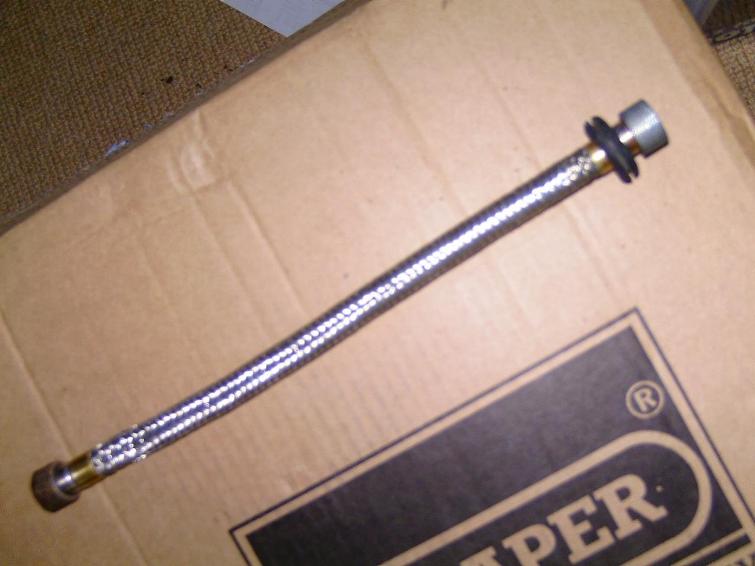
Finally refit the conduit to the vehicle.
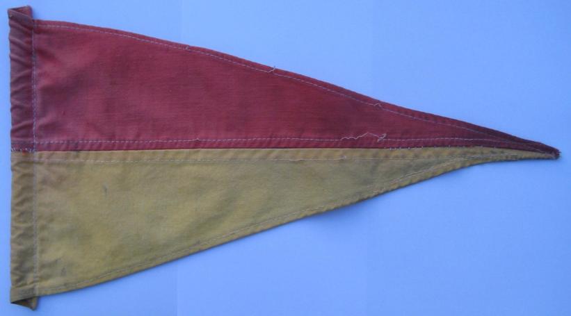
Pennants for the Ferret Antennas / Aerials
Picture and dimensions courtesy of Peter Hall
Dimensions = 34cm from antenna end to the tip, 17cm 'wide' at the antenna end.
Nuts and Bolt Threads
The thread types as used in the Ferret UNF, UNC and BSP. The only metric thread possibly being a nut that holds the windscreen wiper arm on.
UNF is used in / on the hull, engine, gearbox and the wheel stations
UNC is used in / on the gearbox, steering components and the oil tank (commonly used in conjunction with aluminium).
BSP is used with any brass component with a thread - hub plugs, fluid flywheel plugs, grease nipples, sump plug & banjo bolts to name a few off.
Nuts and Bolts Common sizes
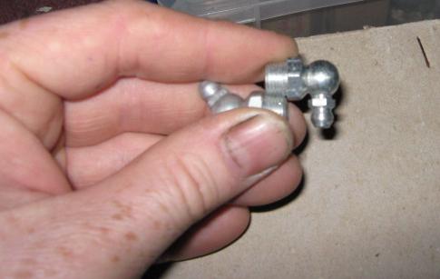
Grease Nipples
All Grease Nipples on the Ferret bar the grease nipples on the prop shafts universal joints are 1/8th BSP, this applies to the early hook on type of grease nipple and the later push on types. The hook on variety can be bought quite readily on eBay UK as can the push on types.
Hook on grease nipple commonly found in early Ferrets.
Later style push on grease nipple (its common to find both the hook on type being used with the later push on varities).
90o Push on type
45o Push on type
A quick way of buying the correct type of bolts (grease nipple in this case) is to take along an original bolt as removed from the vehicle and place it next to the new bolt, the threads should intermesh along the full length of the threads.
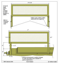
Ferret Basket
Nice and simple and easy to alter for extra length or height
Petrol Cookers Mk2, Mk2 Modified and Mk3 double burner.
All these cookers potentially have an asbestos heat shield it might not kill you today but it will eventually kill you if you do not take the right precautions. You have been warned! See here for more information
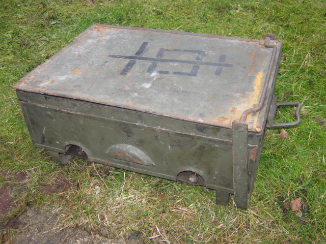
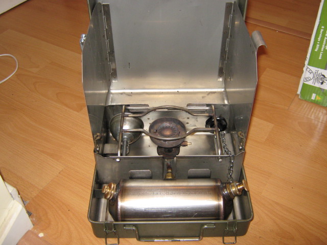
The Mk2 cooker was standard issue CES for the Ferret and many other Petrol powered British Military vehicles. I have a few of these cookers, they all seem to follow a standard design but with different manufactures fabricating them over the years.
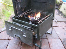
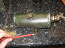
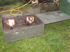
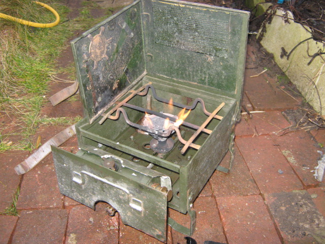
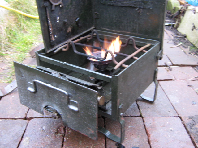
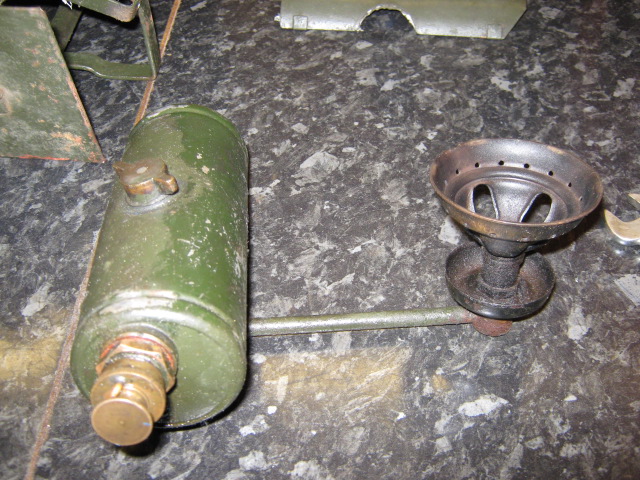
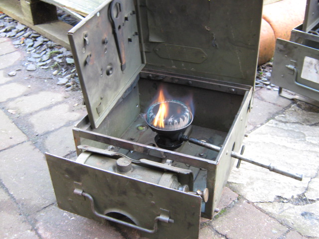
MK 2 Roarer Burner
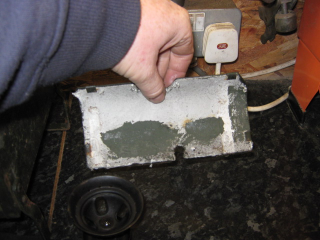
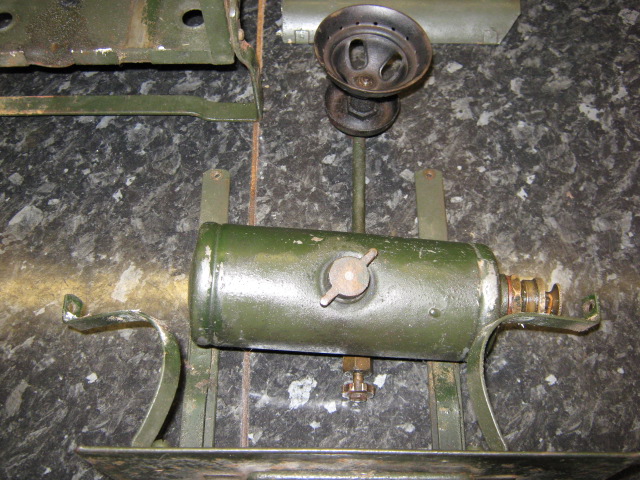
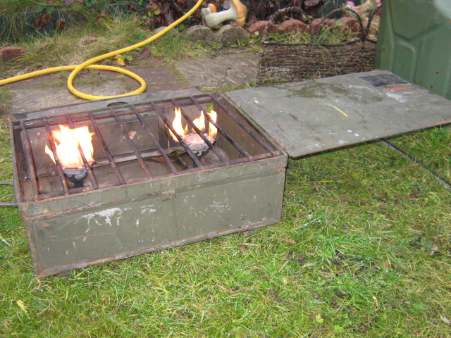
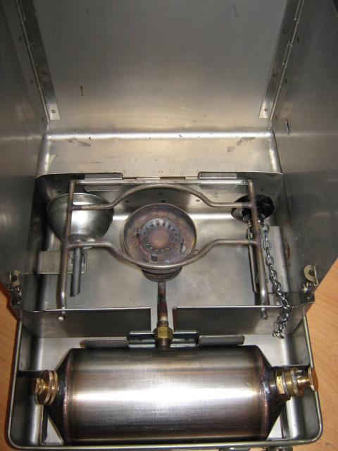
Pictured below is an early MK 2 Petrol fuelled cooker with the roarer type burner and asbestos heat shield. Standard fuel is Petrol (Gasoline) but at a pinch Kerosene and Paraffin will work quite well.

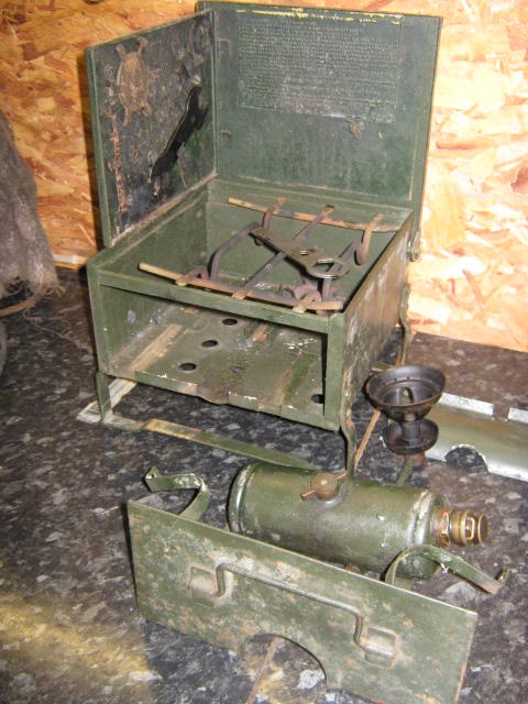
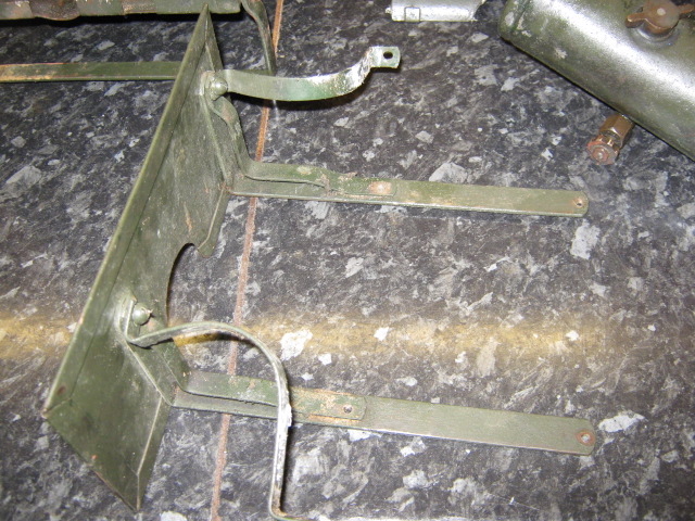
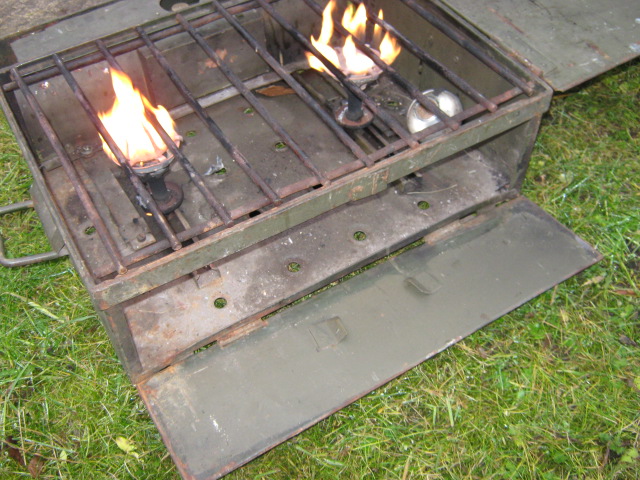
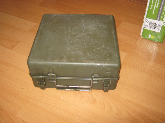
Stripping all versions is quite easy in that two screws retain the tank assembly to the case. Which when removed allow the tank and burner to be slid out of the case.
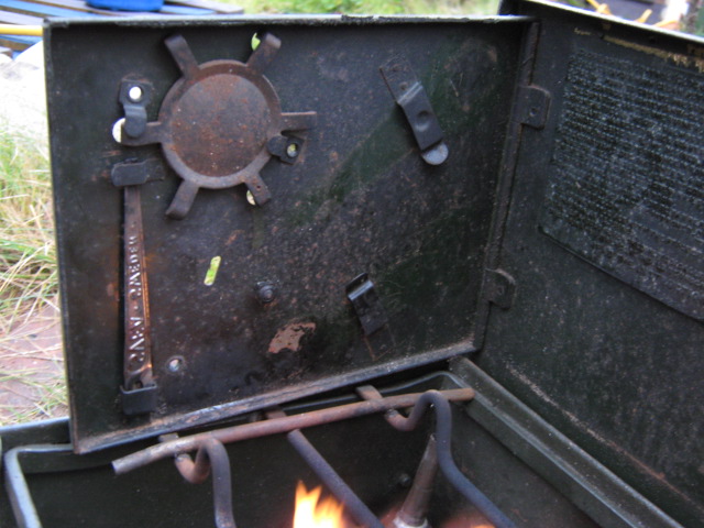
Be very careful with the heat shield as nearly all the early stoves have an asbestos backing to the shield. The heat shield below is dangerous as it is starting to shed its fibres.
Wear a mask and try not agitate the fibres!
Two further screw hold the shield and the tank in place.


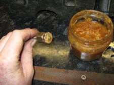
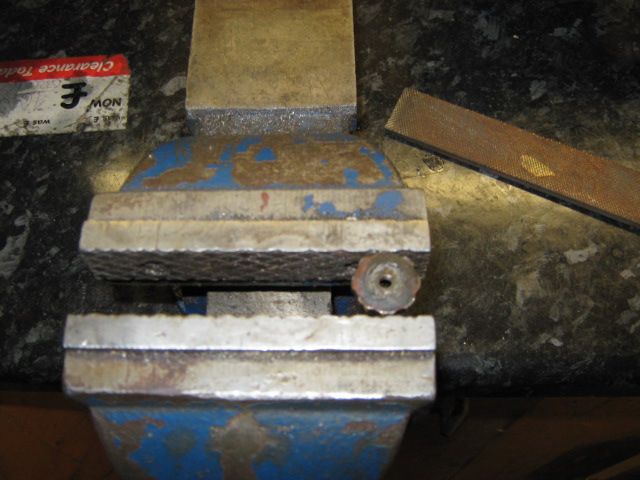
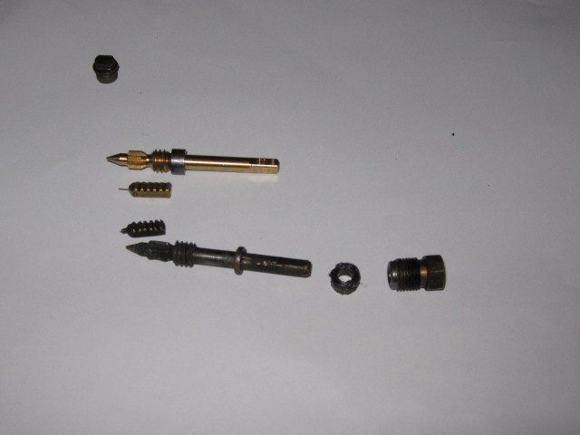
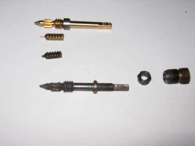
A common problem on early stoves is that the adjusting wheel is soldered onto a ferule and it sometimes comes apart. This ferule is screwed onto the needle which controls petrol flow. The adjusting wheel is made out of brass and the securing nut can be made of brass or steel depending on the manufacturer of the stove (I have seen both). The Steel nut has brass braised onto it to enable it to be soldered.

The rear of the nut has been soldered onto the adjusting screw which is then screwed onto the needle.
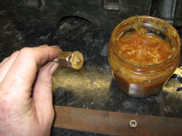
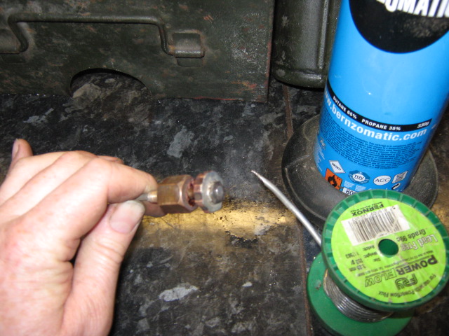
The best way that I have found to repair the offending items is to clean the all the parts back to bare metal with sand paper or a wire brush (scouring pads work quite well also). Dry assemble all the parts back together and then disassemble ready for soldering. Lightly smear flux onto all components that are to be soldered which includes the knurled adjusting screw, the nut and the thread. Reassemble in order and solder back up.
Having played around with these cookers the main problems tend to be:
Non return valve (NRV) sticking to the priming pump.
Leather cup drying out in the priming pump.
Perished filler washer.
Sediment in the tank.
Fibre washer on priming pump not sealing.
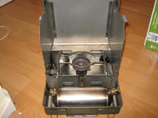
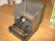
MK 2 modified stove
Standard fuel is Petrol (Gasoline) for the later MK 2 modified stove below. The modified version of this cooker will not run or burn any other fuel than Petrol / Gasoline. Most but not all of the modified stoves will have a stainless steel heat shield.
The Mk 2 modified lacks the front flame control of the earlier cookers and has the flame control moved to the side and is fitted with a different burner assembly. Some early cookers were modified with the new burners so they will still have the front adjustment position sealed off but the control has been moved to the side.
The Cooker below is the first of my No.2 modified cookers that I have managed to have the flame burning blue continuously.
Picture of a stripped version required here
Having played around with these cookers the main problems tend to be:
Non return valve (NRV) sticking to the priming pump.
Leather cup drying out in the priming pump.
Perished filler washer.
Sediment in the tank.
Fibre washer on priming pump not sealing.
Picture required here or a drawing of the valve on the end of the priming pump
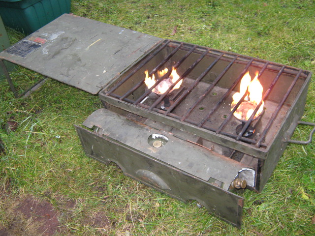
Mk 3 Double Burner
This may look rusty but a good clean of the burners and tank had this running beautifully not bad for a cooker built in 1945.
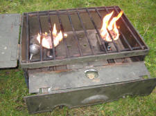
This cooker will burn Petrol, Kerosene and Paraffin quite happily unlike the Mk2 Modifieds.
No 12 Diesel cooker
The MK 2 and MK3 petrol cookers were replaced by the No 12 Diesel cooker which in many ways is superior to the early petrol cookers in that its easy to clean and strip apart and it works. Not part of Ferret CES but its a great portable cooker.
I use Kerosene as the fuel in my cooker but Paraffin and Diesel can also be used. The No.12 Stove is not suitable for petrol.
I have a No.12 cooker that has no flame control its either spurting fuel or there is no pressure in the fuel tank.
The company who manufactures these cookers will now supply spares to the public but you can also use Optimus Stove spares as well.
The new Optimus parts are shown below, the spindle is almost identical but the ratchet part with the needle on it has an extra tooth and may require some modifications with a small file. If you look closely at the lower 'dirty' spindle you will see that the teeth have been scrunched and the ratchet / needle also shows damage.
No. 12 Manual here
* New spindle
2191 Regulator spindle for burners 2004, 9000, 9001, 9003. Stoves 5R, 7, 10, 11, 111C, 535 Kero
* Graphite packing
2094 Graphite packing for burners, 207, 209, 221, 222, 2004, 2018
* 6 tooth needle
2455 Cleaning needle, 6 tooth, for old stoves 22, 111, 111B, 535, Marine stoves 154 & 155, Oven 156
A few tips were gained by looking at the forum below.
http://www.spiritburner.com/fusion/index.p
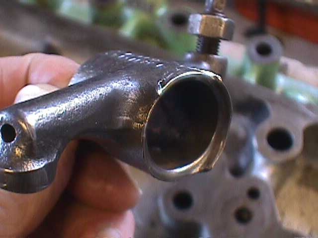
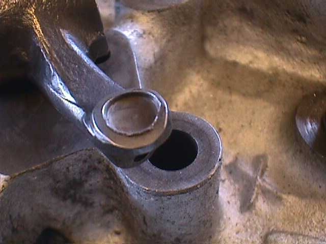
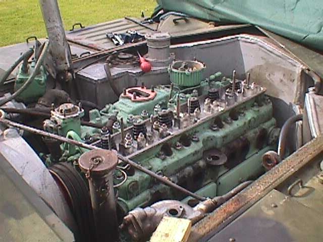
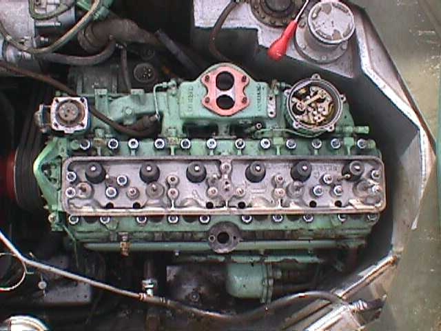
Timothy Rendall's five cylinder Ferret
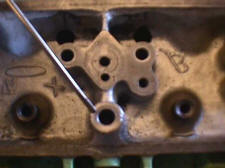
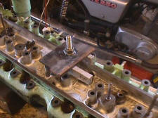
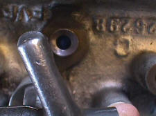
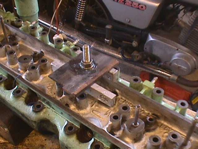
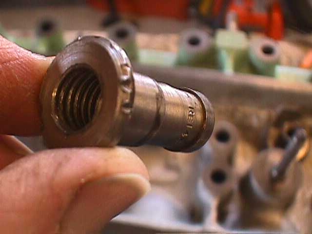
The Ferret had been running on five cylinders when I bought it and I have now found out why. The oil feed to the head was blocked I had to take out the centre bush shown in photo but to do it I had to make a jig to extract it.
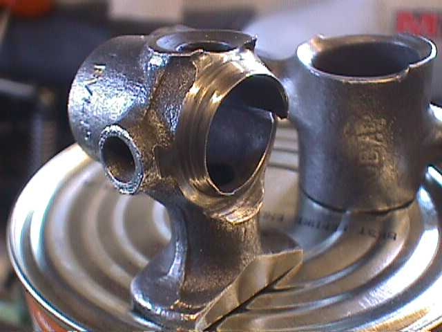
I’ve put in new valve guides and second hand rockers as you can see they were 'us'.


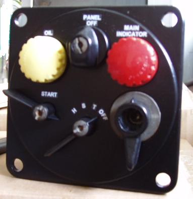
Replacement Switchboard Letters
I needed to rebuild an early switchboard stripping and painting the switchboard was the easy part reapplying the original letters and having it look reasonably o.k. was the difficult bit. I am not going to claim that this was my idea as it would be nothing new to a model kit maker.
Click the picture and a word document will pop up in a new window with instructions on how to do it.


Electrical Problems
It's what happens if the main ignition feed from the main switch panel to the engine junction box isn't properly clipped up, or the clips corrode through.
The cable drops and rubs on the drive shaft/bevel box flange which eventually wears through the casing. This usually starts with the engine cutting out intermittently, gradually getting worse until the electrics are dead. You can hear the distribution box relay trip and re-set.
As the contact isn't direct, a standard Multi meter doesn't show the short, but 24v easily jumps, creating the short. A new cable is £90 and a pain to replace. The clips also hold the main alternator / generator cable which is a bit more substantial (£££) and will probably destroy the rectifier if it shorts.
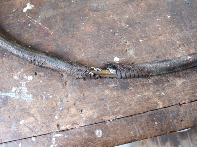
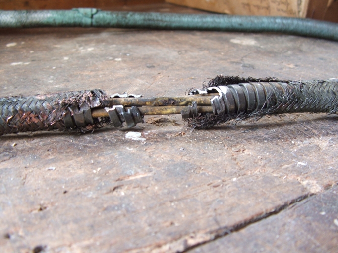
I noticed the same problem on my Ferret when I was putting my Ferret back together my solution was to use tie wraps (cable ties) its an inexpensive solution that only the owner will know about and if it saves ££££ / $$$$ well worth doing.
Many thanks to Dave Rose for passing the above information on.
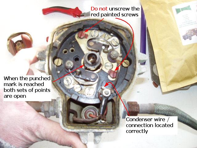
B60 Distributor
Stencils
At the time that I am writing this its just after Christmas, I have chocolate boxes a plenty and decided that some of the surplus card could be used to make a simple stencil. The vast majority of the writing or basic images would have been painted on.
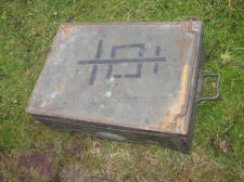
External First Aid box Stencil
Click the picture and a new window should open with a pdf image off the picture below. Save the pdf file to you're computer and then select Control & P (Ctrl & Print). For picture or page scaling select none as you want the picture to be printed to the exact size that it was drawn in the original document.
Rear Convoy Stencil
Click the picture and a new window should open with a pdf image off the picture below.
Antifreeze Stencil symbol
As painted onto the underside of the rear deck above the radiator cap.
Click the picture and a new window should open with a pdf image off the picture below.
Bridge Plate Stencil
Click the picture and a new window should open with a pdf image off the picture below.
Just the No. 4 on its own

Petrol Tank
Diagram of the Petrol Tank and Change over Tap
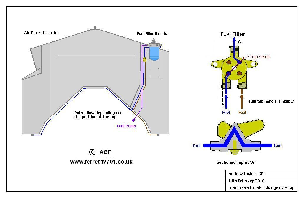
Change over Tap
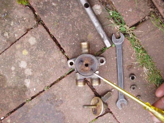
When I was first setting up the petrol tank on 00CC09 I found that I had a problem with the change over tap in that it would not let any petrol flow through the tap handle. To add insult to injury their was a leak in the Filter bowl itself. I had no other choice but to strip the tap down, when I stripped it down I found that the handle itself was clogged as was the body of the unit. Cleaning the tap and the body resulted in a damaged cork gasket which I then had to replace, which isn't a difficult as it sounds. The cork gasket is quite easy to make as the hole pattern is just the same as five on a dice. The cork gasket has locating lugs to stop it rotating when the handle is turned.

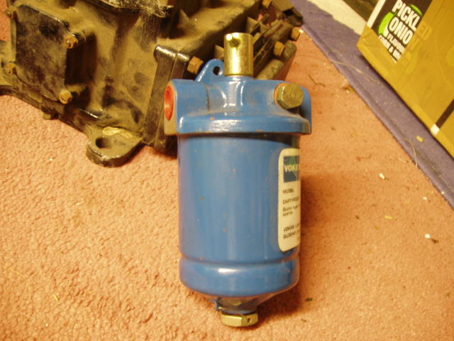
Vokes Filter bowl
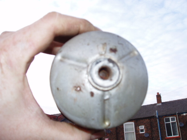
Clean the bowl out when a new filter is required and clean away any sediment and check for holes in the filter body. If any holes are found in the bowl it might be repairable if the rust inside is sandblasted away and it then has the hole brazed up with brass. The bowl would have to be cleaned throughly before blasting (no smell of petrol)!
I enlarged the hole in the filter bowl for the camera.
After my own experiences I would suggest cleaning out the bowl and replacing the filter element if the vehicle has been standing for an unknown length of time. It would also be good idea to clean the tap out as well and fit a new cork gasket. Don't forget to clean the little filter on the carburettor in feed pipe if your doing the above.
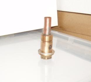
Banjo Bolt modification
I can not claim this modification as my own it was found on a petrol tank that I helped remove in South Wales, a past REME modification when and where who knows.
Banjo Bolt with a one inch brass extension tube / Purpose to stop sediment from the bottom off the Petrol tank being sucked into the system blocking the petrol filter / banjo bolt filter. Occasionally sediment bypasses the main Petrol filter and is only stopped by the smaller filter at the banjo bolt on the Carburettor which eventually blocks stopping the engine. This modification lifts the Banjo bolt in-feed off the bottom of the tank. It only needs to be recessed into the Banjo bolt by 1/8th of an inch and it is then soldered into place.
Picture off a duff bolt which has a crack across one side with a copper tube to illustrate the drawing.
Extremely rough job on my part to illustrate!

Priming the fuel system on the Ferret
Vokes Filter set up in the Ferret and a Vokes Filter body
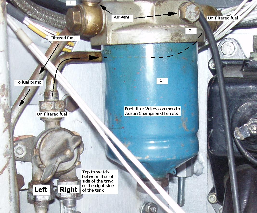
This is what I do when I prime the fuel system on a Ferret it is worked every time for me.
When writing about left and right I'm looking directly at the Fuel tank with the Vokes filter on my right.
For this to succeed safely you MUST remove the batteries from the vehicle, sparks and petrol don't mix! Unless you like the idea of being fried alive or having a super rapid tan! I would also suggest that this is a two man job. The 2nd person is there to hand you tools, cloths, help and laugh at you while you're doing the majority of the work.
The 'work'
Label up the battery cables + / - and then remove cables from the battery's left hand side first.
Disconnect and remove both batteries and the battery box under the inter-vehicle starting box. Remove the middle gearbox support on the side that the battery box was removed from. You can now gain access to the priming handle on the fuel pump. Reach your hand in under the fuel tank and feel for the pump, the priming handle is on the thumb side when the pump is cupped with your right hand. With the thumb press on the handle and feel if there is any resistance (not easy to quantify), if fuel is already in the system you might hear it attempting to suck / draw fuel to the pump.
Place a cloth under the fuel tank under the filter, loosen off but don't completely remove the T shaped handle on top of the filter body. The blue filter body (in these pictures it is blue) should now drop down by about a centimetre / 1/4 inch. The unfiltered petrol pipe coming from the top of the tap in the picture above stops the filter body from dropping to far.
Fill the filter bowl with petrol no.3 in the picture (it might run over the top) the cloth underneath is there to catch any petrol drips, retighten the T shaped handle which should bring the filter bowl up to the sealing ring.
Undo and remove the air vent no.1 in the picture to a safe place (assistants hand no chance of dropping it) and fill the pipe with petrol all the way to the top. Re place and tighten the vent up.
Undo and remove the air vent no.2 in the picture to a safe place (assistants hand no chance of dropping it) and fill the top of the filter up with petrol, once it is full replace and tighten the vent up.
Reach your hand in under the fuel tank and feel for the pump, the priming handle is on the thumb side when the pump is cupped with your right hand. With the thumb press on the handle and start priming the pump, it could take up to ten strokes to prime the pump. It should be possible to feel the priming handle stiffing up when fuel has reached the pump / carburettor. A quick way of testing to see if fuel has reached the float chambers in carburettor is to remove the carburettor air horn and operate the accelerator rod. Two jets of petrol should shoot into the carburettor indicating that the float chambers in the carburettor are full.
Replace batteries and operate the starter Ferret should now start.
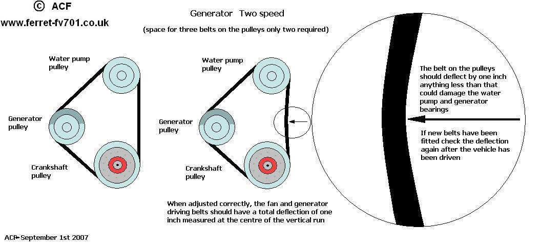
Generator
(Dynamo or Alternator)
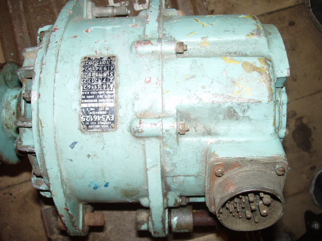
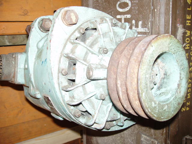
If it is a Dynamo it will say Generator No.2. The picture below shows the No.2 Dynamo at the top of the picture.
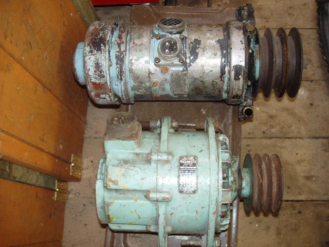
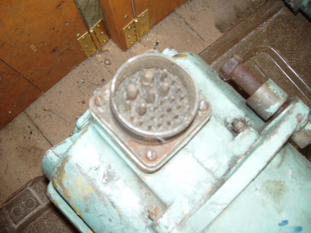
Identifying features for the Generator No.2. (Dynamo). Grill on the top off unit next to the plug and oil pipes running to the Dynamo from the engine block. The rear end of the Dynamo is fluted with a grill and the unit has no cooling fins. The pulley has the capacity for three belts (same as the Alternator) but only two belts are fitted.
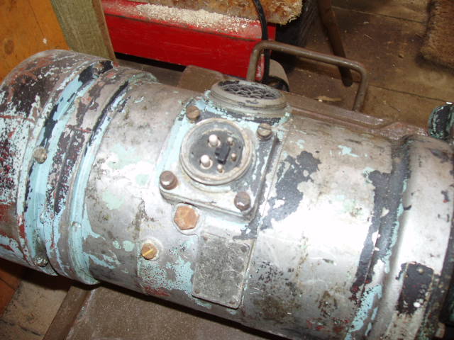
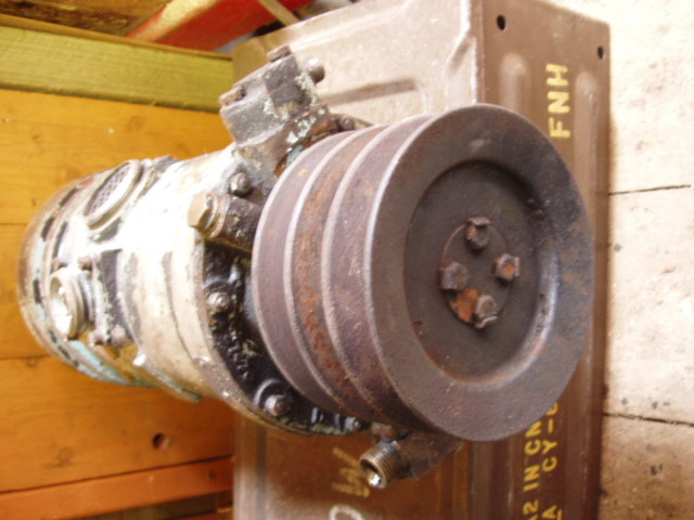
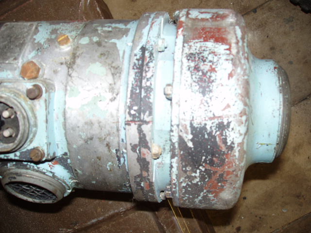
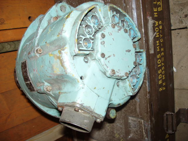
If it is an Alternator the plate on it will say Generator No.10. The picture below shows the No.10 Alternator at the bottom of the picture.
Identifying features for the Generator No.10. (Alternator). A large plug connection is fitted at the opposite end to the pulleys and has cast in cooling fins at either end of the Alternator. The pulley is designed for a narrow car type V-belt (three belts fitted).
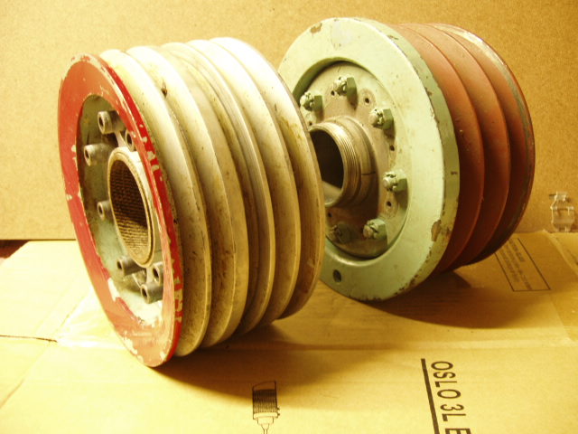
Alternator and Dynamo engine crankshaft pulleys. Dynamo crankshaft pulley and Alternator crankshaft pulley (first picture) reversed in the next.

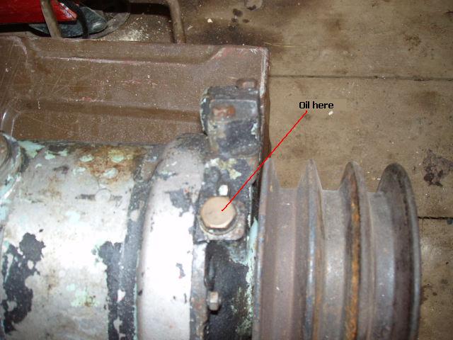
Generator (Dynamo) belt tensioning
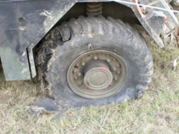
Wheel Station
A damn good reason to replace twenty plus year old tyres.
Tyre Pressures
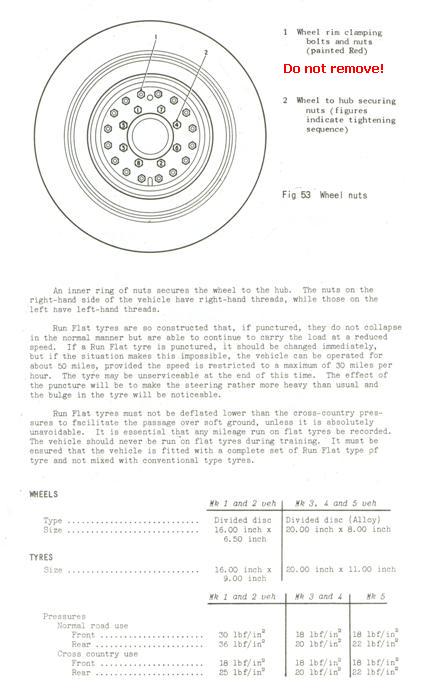
| Normal Road Use | Marks 1 to 2 | Marks 3 to 4 | Mark 5 |
| Front | 30 lbf | 18 lbf | 18 lbf |
| Rear | 36 lbf | 20 lbf | 22 lbf |
| Cross Country | |||
| Front | 18 lbf | 18 lbf | 18 lbf |
| Rear | 25 lbf | 20 lbf | 22 lbf |
Brakes


Steel or Copper Brake pipe lengths inside the Ferret hull
From the Left hand side rear elbow approx 94 inches long
From the Right hand side rear elbow approx 98 inches long
Connection pipe from left side to master cylinder inches ** long
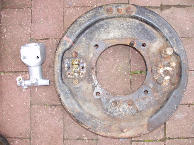
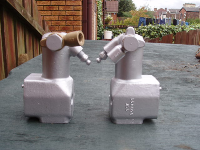
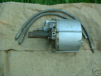
Brake Booster (Servo)
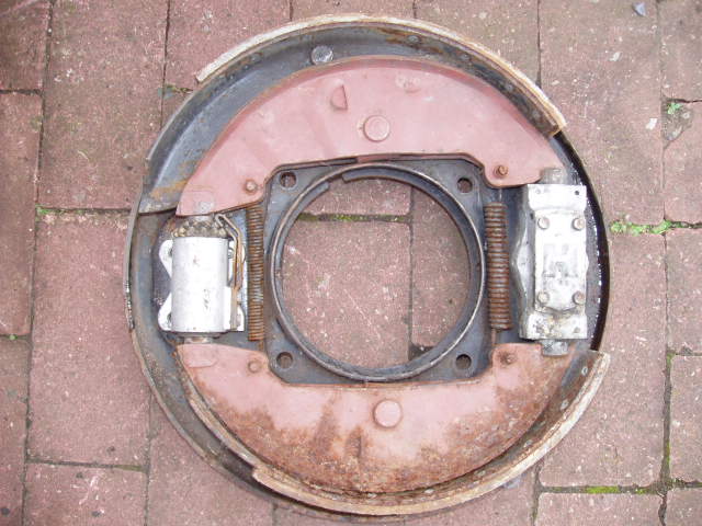
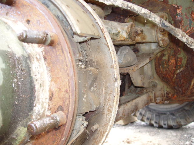
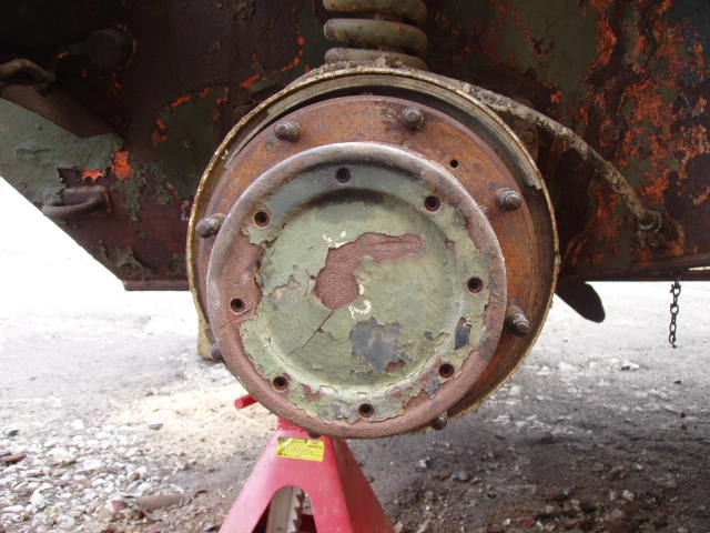
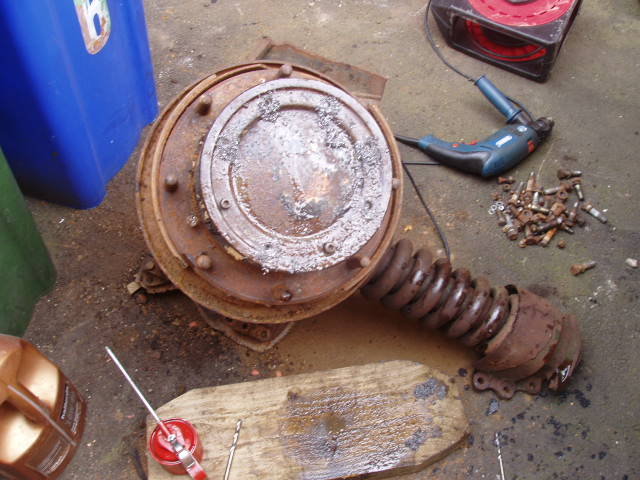
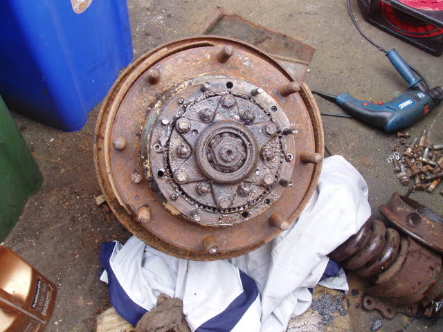
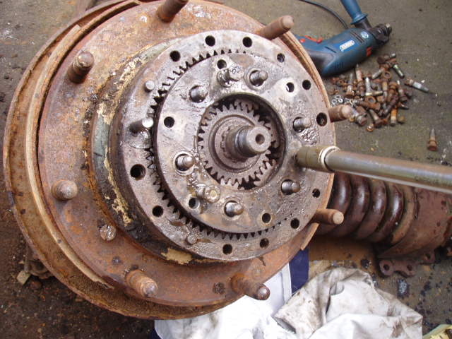
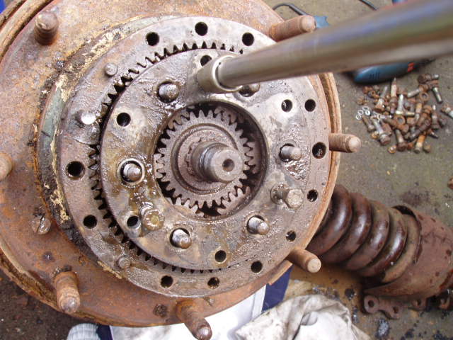
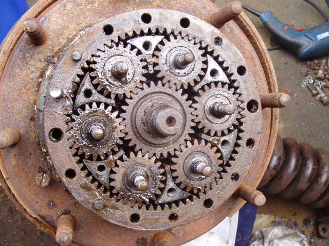
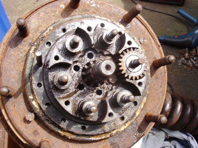
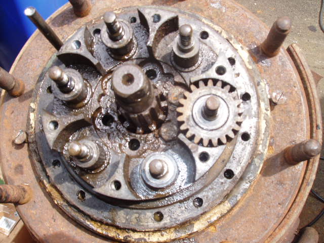
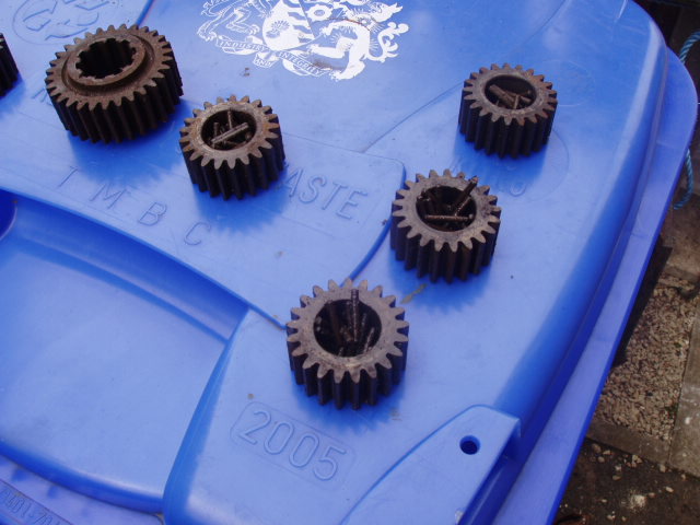
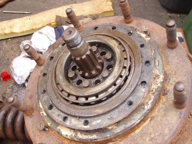
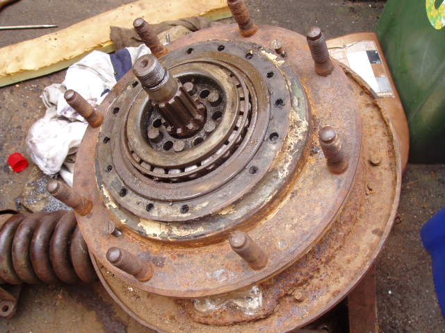
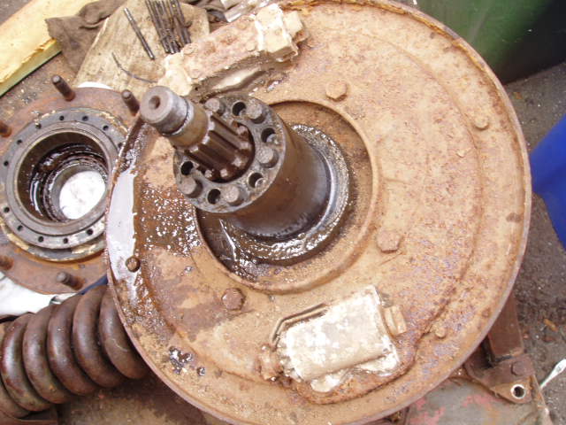
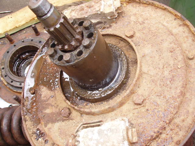
Wheel Hub
I was given a wheel station (hub / bevel box) that was still mounted to a small piece of armour plate. The wheel station below had seen better days so I stripped it down to help me understand the workings of the hub and the planetary gears. Before I started stripping the wheel station down I'd always been wary about stripping down a hub, having done it I now cannot see why I was so bothered! The worse bit was removing the eight allan headed bolts on the hub face all but one was seized in place!
The the brake linings are / could be made of asbestos you have been warned!
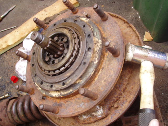
I'll list the basics and I mean basics off stripping it down
Tools needed:
Mask consider the brake linings to be made off asbestos and treat accordingly!!!
Hammer normal and plastic faced, flat bladed screwdriver large and small, cir-clip pliers,1/2 spanner, 9/16 spanner, 7/32 allen key, Impact driver, two 1/2 inch by 1 and a half inch bolts, 2 x 19mm spanners or imperial spanners, 19mm socket or imperial equivalent, 1/2 inch & 9/16 sockets,


| Capacities | Key | Imperial | Metric (litres) | Oil Specs Military | Oil Specs Civilian |
| Steering bevel box (upper) | 1 | 1½ pints | 0.85 | OEP-220 | 90EP Gear oil |
| Steering cross-shaft bevel box (lower) | 1 | 1½ pints | 0.85 | OEP-220 | 90EP Gear oil |
| Inner tracta joint housings, including bevel boxes | 2 + 10 | 3 pints | 1.7 | OEP-220 | 90EP Gear oil |
| Outer tracta joint housings, including road wheel hubs | 3 + 11 | 1½ pints | 0.85 | OEP-220 | 90EP Gear oil |
| Front and Rear Prop shafts | 4 | Three grease nipples per shaft | Multi purpose grease | ||
| Transfer box | 5 | 6 pints | 3.41 | OEP-220 | 90EP Gear oil |
| Gearbox | 6 | 1¼ gal | 5.7 | OMD-110 | SAE 30 straight |
| Air cleaner | 7 | 4 pints | 2.28 | OMD-110 | SAE 30 straight |
| Fluid coupling | 8 | 9¾ pints | 5.52 | 0M13 | ISO10 or ISO15 |
| Engine lubrication system (dry sump) | 9 + 12 | 3 gal | 13.64 | OMD-110 | SAE 30 straight |
| Engine cooling system | 13 | 4½ gal | 20.46 | Not spec. | Antifreeze |
| Fuel Tank - total including 3 gal reserve | not in pic blw | 21 gal | 95.5 | N/A | N/A |
| Brake fluid supply tank | not in pic blw | 1¼ pints | 0.71 | OF-20 or OF-24 | Dot 3 / 4 |
![]()
Last updated on the 16/02/2015 23:37 Copyright © 2007 - 2015