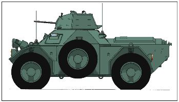
Daimler Ferret Engine and Gearbox
Last updated on the 16/02/2015 23:44
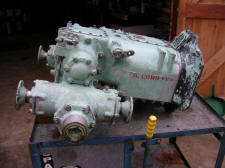
B-60 Engine & Fluid flywheel Dry weight of Rolls B60 engine including fluid flywheel is 812 pounds The engine complete with fan assembly, radiator, oil tank, gearbox and transfer case is 1428 pounds (EMER 624).
British Standard Paint colours for the engine and gearbox Sky Blue BS101.
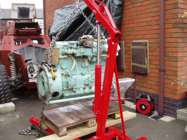
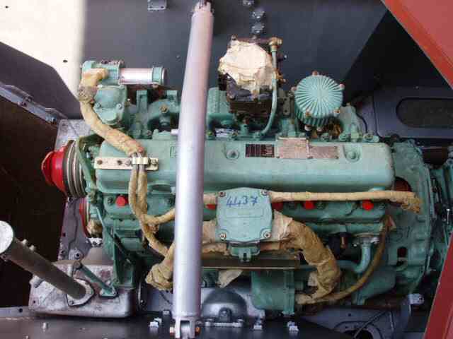
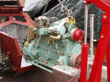
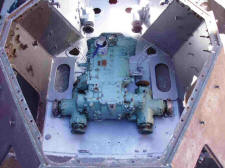
B60 on it is pallet before it was fitted
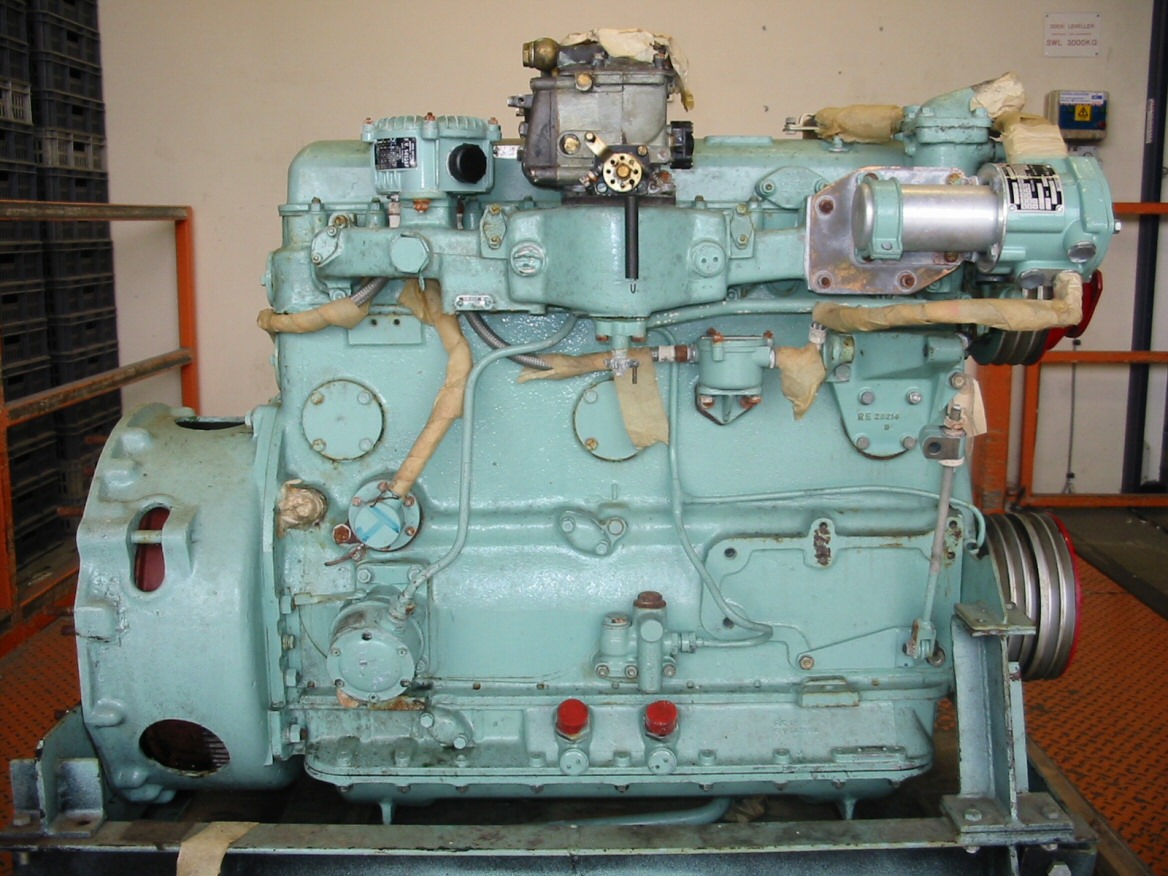
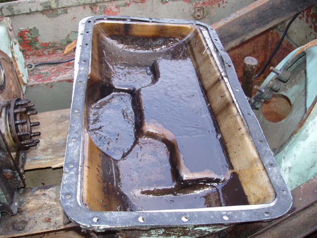
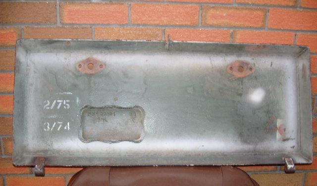
Dry sump or oil tank whatever is your preference with the rails which are adjustable at the collars next to the sump.
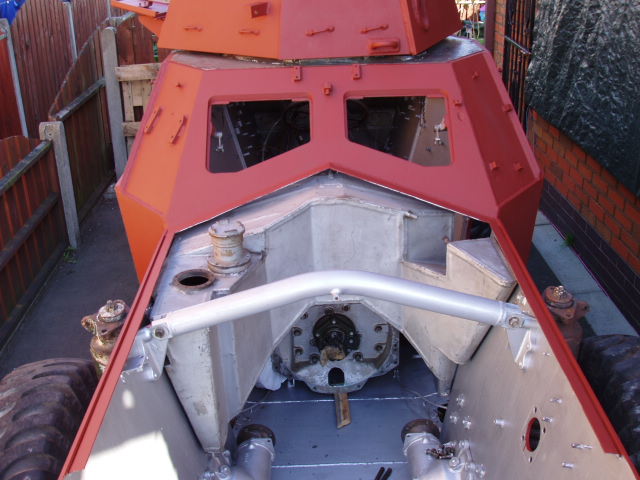
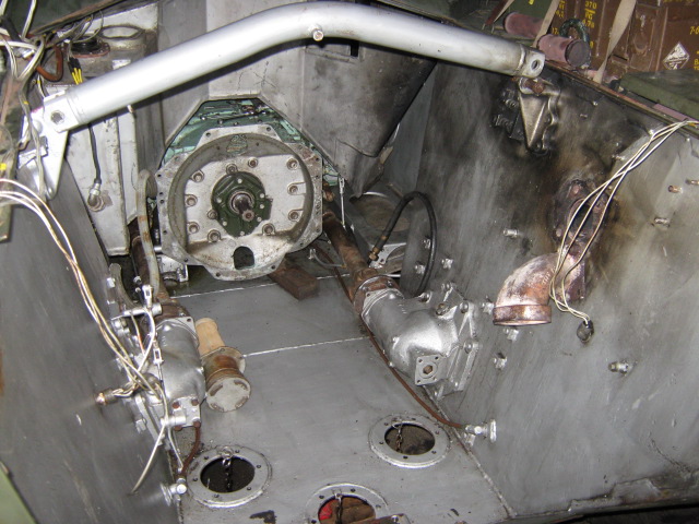
Before the engine was refitted the hull cross tube was removed and the petrol tank was pulled back into the compartment.
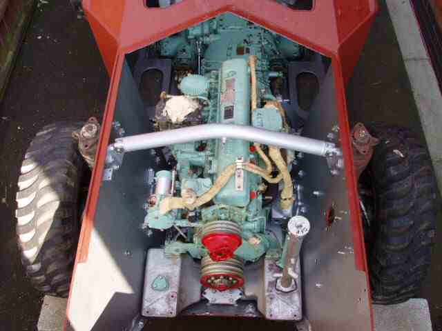
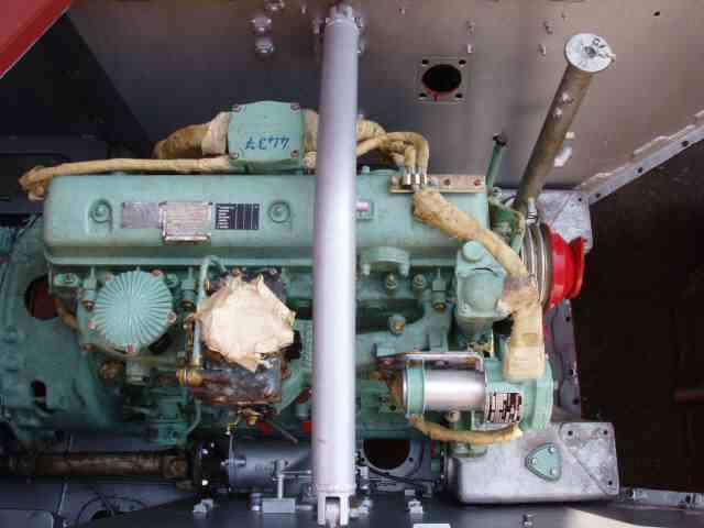
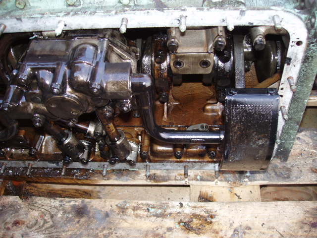
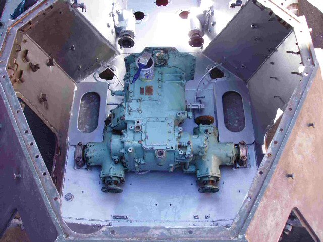
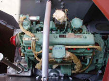
Fitting the engine and after nearly everything was connected up
Spot the mistake... I'll give you a clue oil pipes


Engine removal
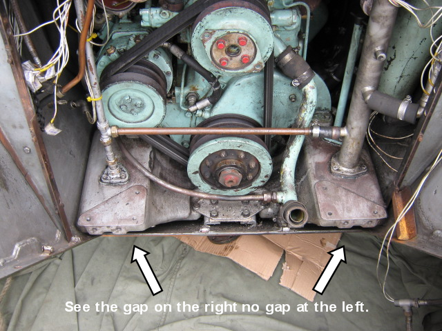
Unfortunately I hadn't realised that the collars were adjustable on the rails that join the sump to the rear mounting plate and the first picture shows the result.
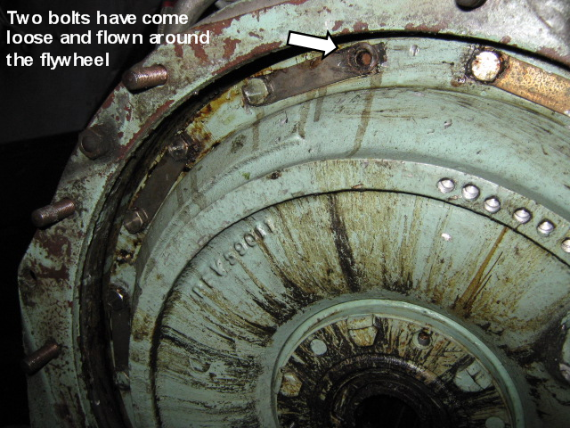
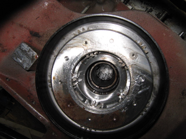
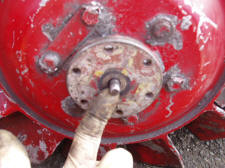
After removing the engine I noticed that two bolts were missing from the fluid flywheel one may have been removed by the head of another. It shouldn't have been able to come loose due to the locking tabs?!
This is what a cracked exhaust elbow does to nice shiny silver paint. Oh did I forget to mention how clean-ish the floor is as well, it had a nice protective coating of oil from the reconditioned / new engine.
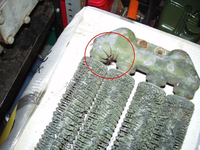
Spider hidden in the Oil cooler coils
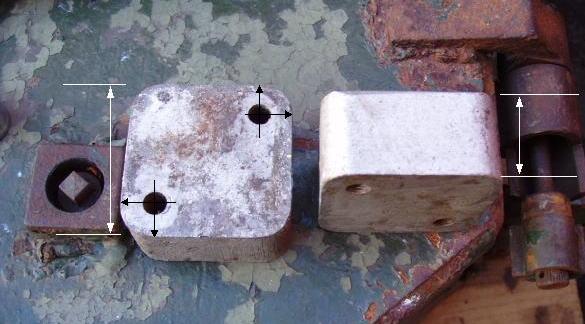
Engine mounts solid Aluminium
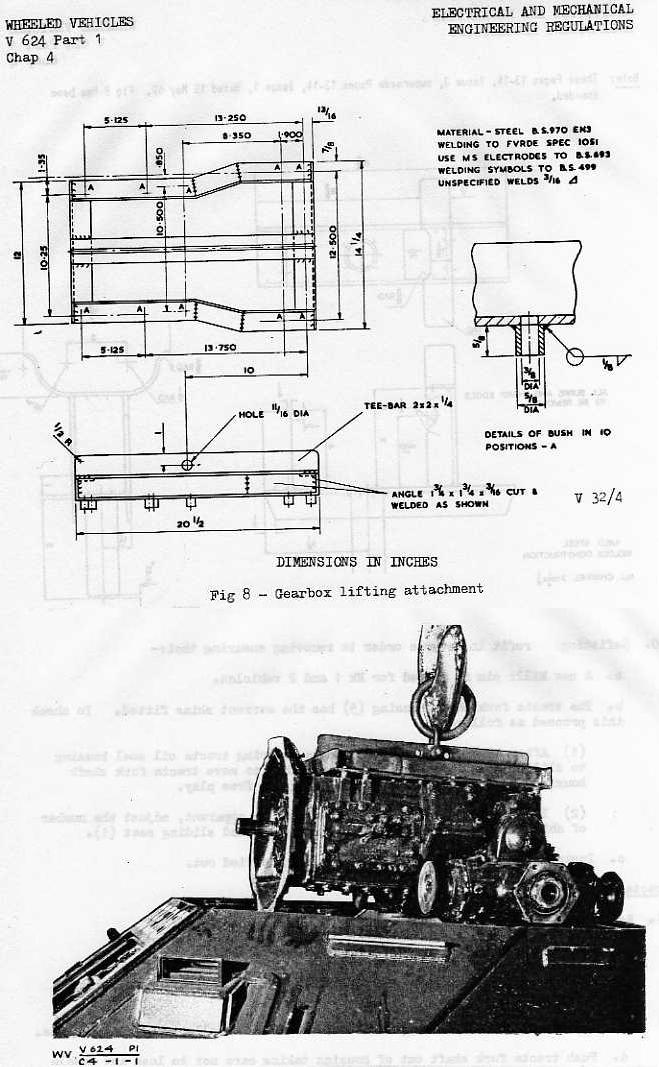
Engine and Transmission Lifter drawing
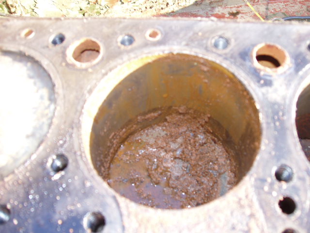
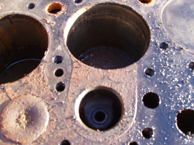
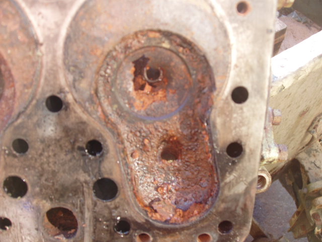
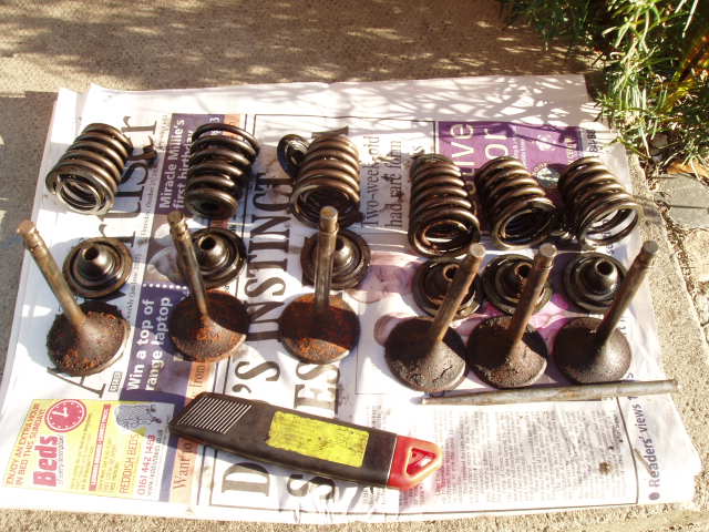
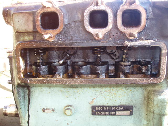
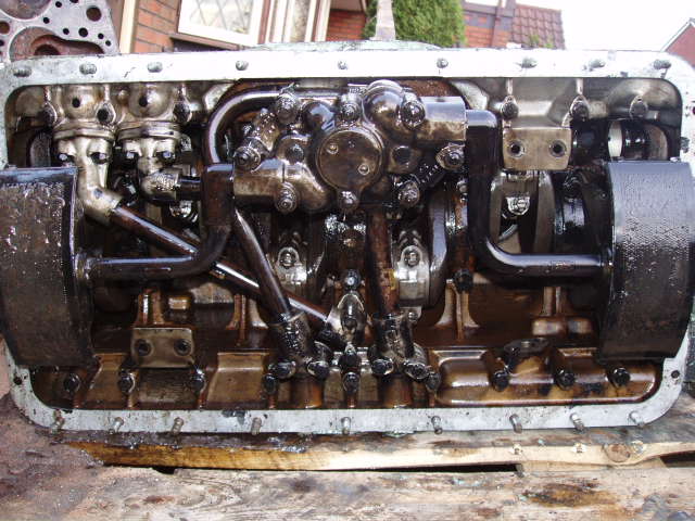
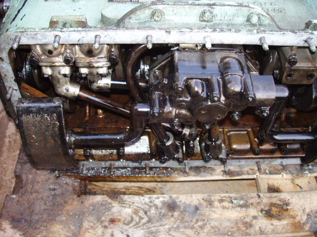
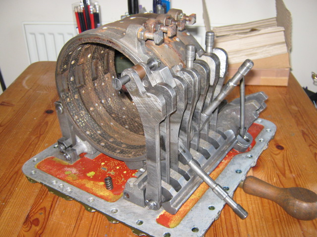
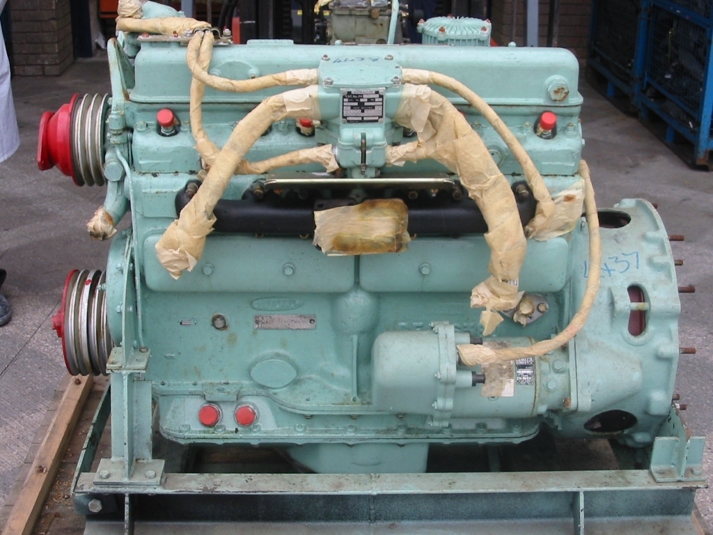
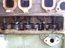
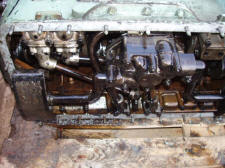
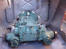
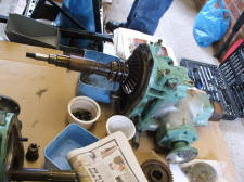
Scrap B60 partially stripped down
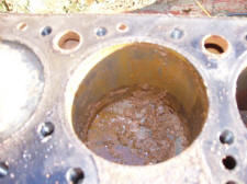
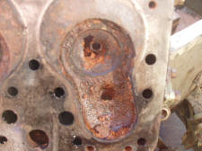
The B60 has the inlet valves mounted in the cylinder head and the exhaust valves mounted in the block (I over E) today it would be considered to be a rather archaic design feature, but not uncommon in the 1940's - 1950's
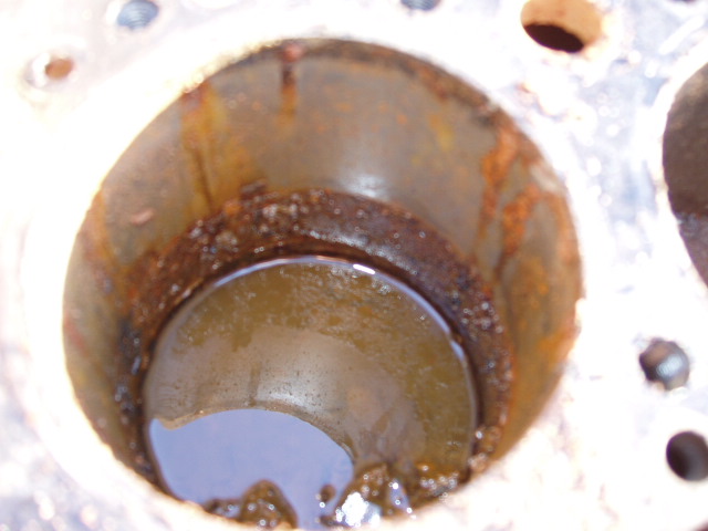
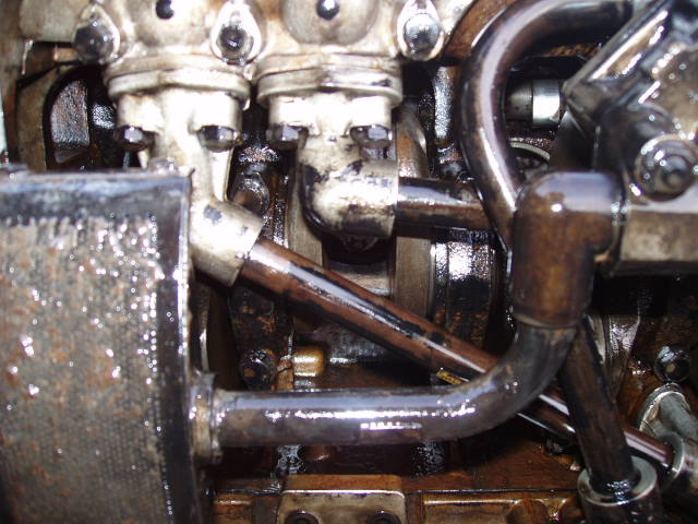
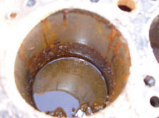
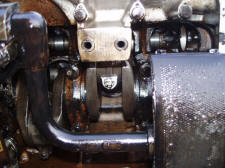
Oil pick up pipes

Close up and the oil collector plate

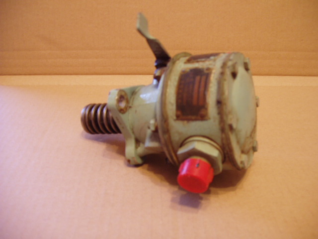
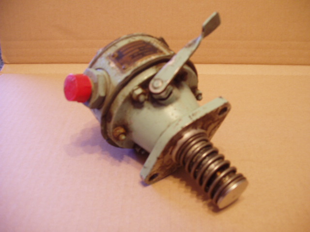
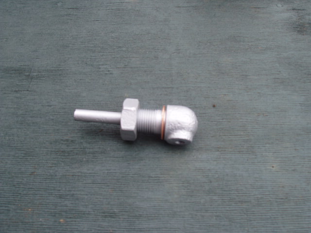
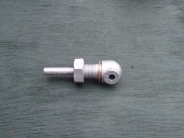
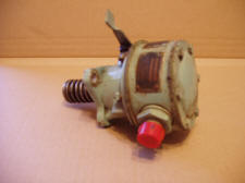
David Fuel Pump
Click here for servicing the David Fuel Pump
Cooling system
Radiator overflow hull mounted
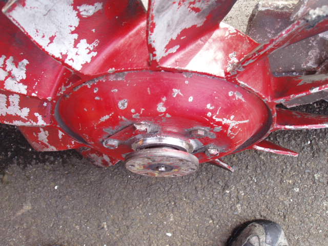
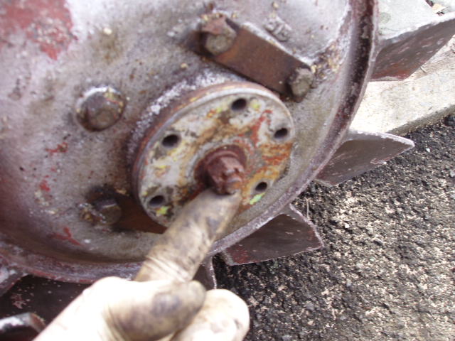
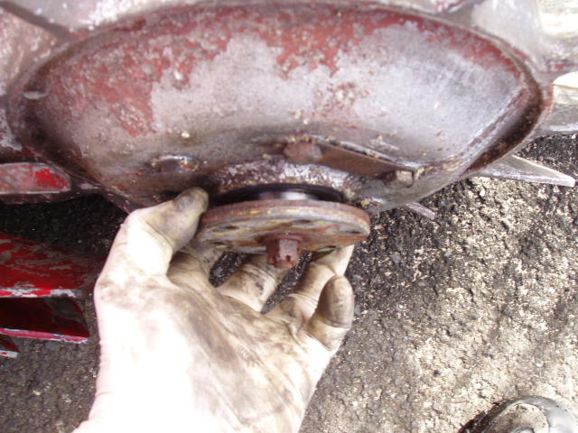
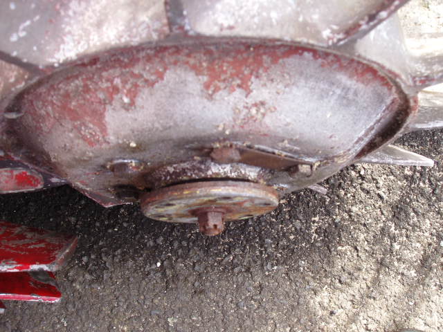
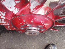
Fan
Red fan bearing gone, nut / split pin missing and metal removed from the fan itself. Silver fan; bearing fine nut / split pin rusty, removed split pin and replaced with another. Engine requires shimming under the solid engine mounts on top of the sump and the collars on the tubes require adjusting also to square the tank and fan cowl up. As soon as my hydraulic ram for my engine lifter comes back from repair I'll be contemplating removing the engine... oh joy!

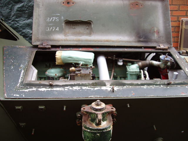
Anti-freeze mark painted on the underside of the hatch (carburettor side) white square with a red circle

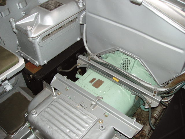
Battery leads over the gearbox
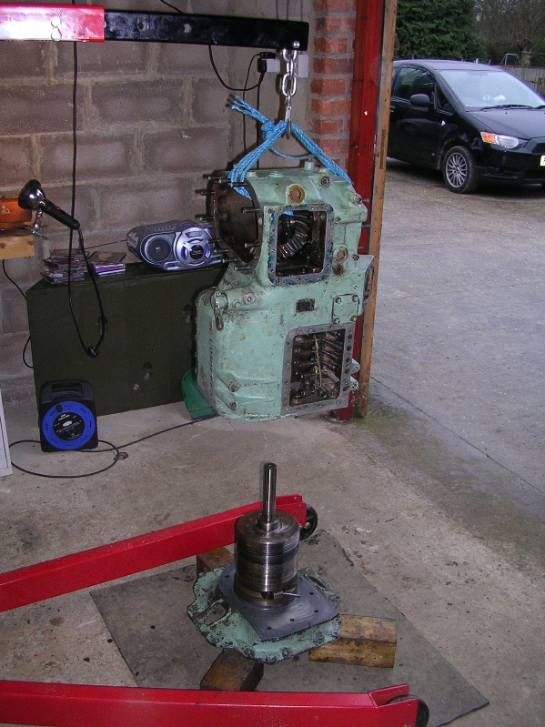
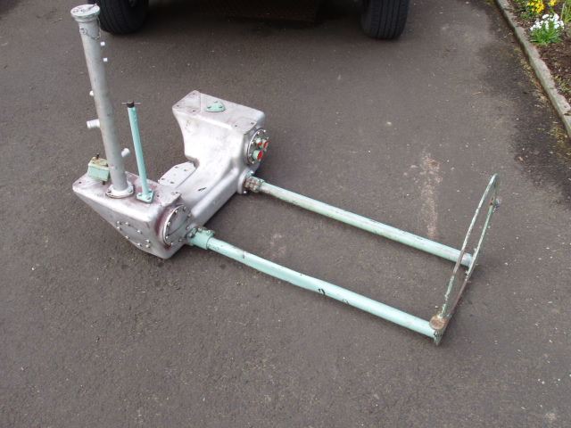
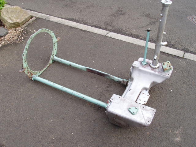
Gearbox Lifting frame
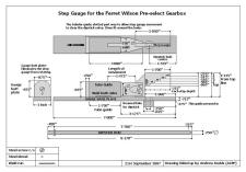
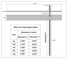
Australian Step Gauge for adjusting the bands on the gearbox.
British Army version for adjusting the bands on the gearbox.
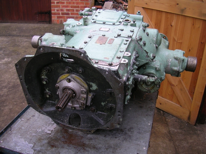
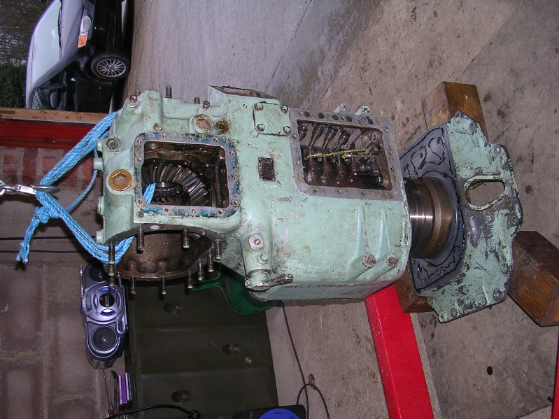
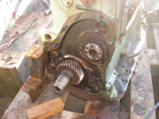
This is off the Gearbox of 08BB48
It has required a full strip down due to it being open to the elements (water) and foreign bodies no dipsticks fitted.
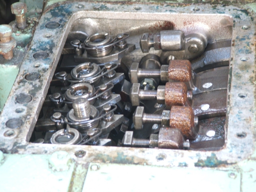
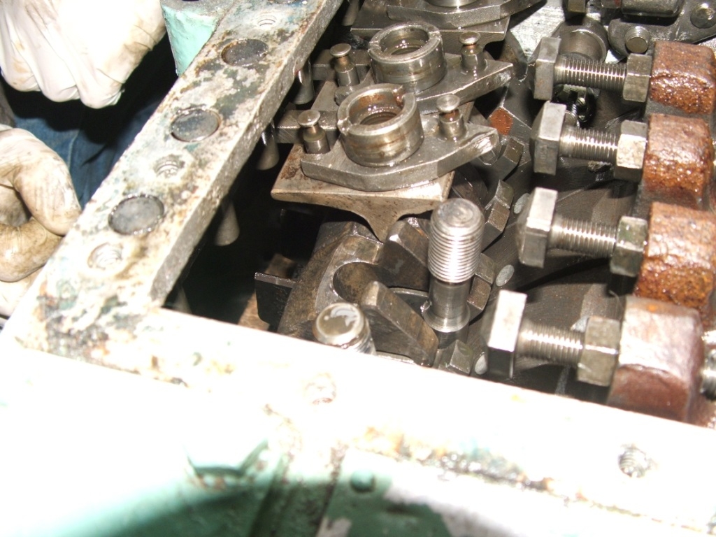
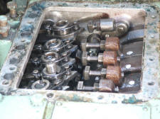
Do not undo the six castle nuts with there split pins. I removed the split pins (cotter pins) and replaced them with new ones.
If you undo all this could potentially drop into you're gearbox and if you haven't already banged you're head against the hull you soon will be in frustration!
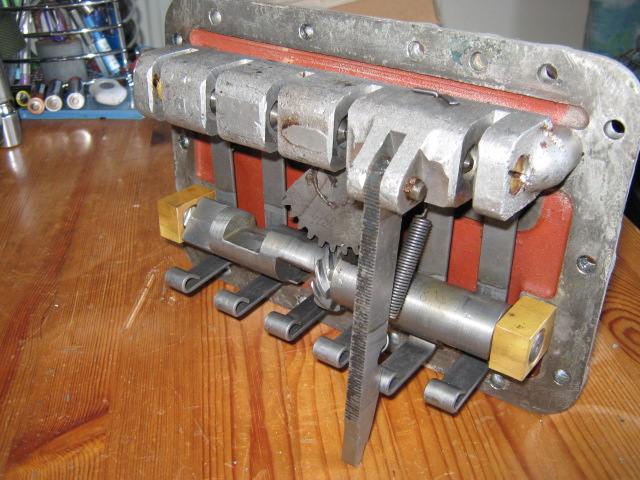
Also beware that camshaft has two centre punch marks that correspond with the centre punch marks on the segmented gear. Reassemble it wrong and you will miss a gear selection. If you look carefully this has been set up incorrectly, the punch marks don't correspond with the camshaft.
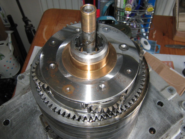
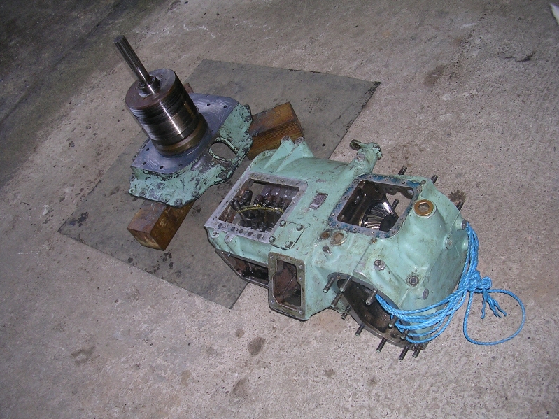
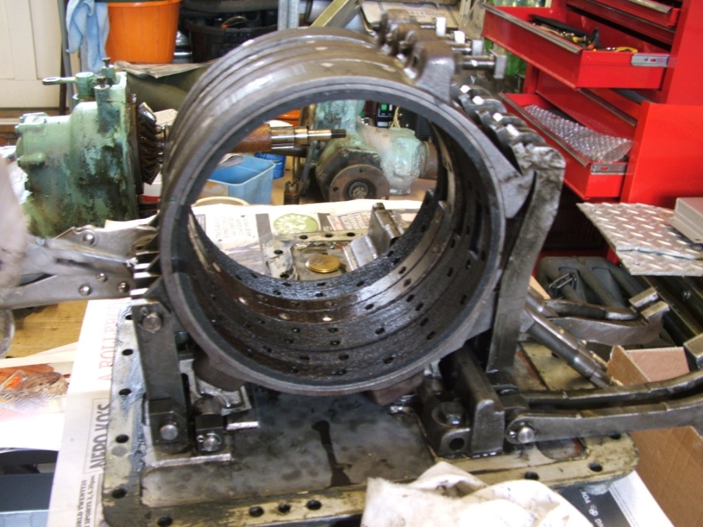
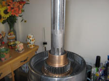
Looking up into the gearbox with the tip of the dipstick at the very top centre. This plate has to be removed and placed on top of the bands below. My plate and gear train was some what reluctant to leave its home of twenty plus years.
Its a wonderful piece of engineering only really spoilt by some light corrosion due to the oil and water mix. I would have taken more pictures of this gearbox but I had very little space to move about in.

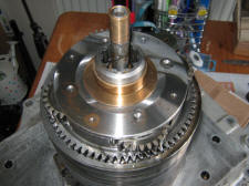
Jim Davies has supplied a few extra pictures that show some of the reassembly of a gearbox which I'm very grateful for.
The gearbox is being dropped onto the drums. Use plenty of sealant as well especially around the bolt holes. Watch out for the fifth gear strut! Its very easy if you're not careful to catch it on the side of the hole when the box is being lowered down (tuck it in and watch your fingers).
Dave Rose Gearbox Band replacement
Dave Rose has supplied a few pictures and a cracking description of the fun that can be had rebuilding the gearbox. I have left most of the pictures at the size that I was sent them just to make it easier to see how it all comes apart.
Unfortunately you will have to remove the gearbox from the vehicle for this job which would be o.k. if its a MK1 but if its a MK 2 the turret has to come off.
Do hire a gantry from you're local hire shop, a normal engine crane will lift the turret off but you might not survive the turret falling on you when the crane falls over. Don't scrimp on this cough up you're money and do it safely!
Providing you follow the manual (beware, the sections do jump around a bit), it's fairly straightforward, if fiddly at times.
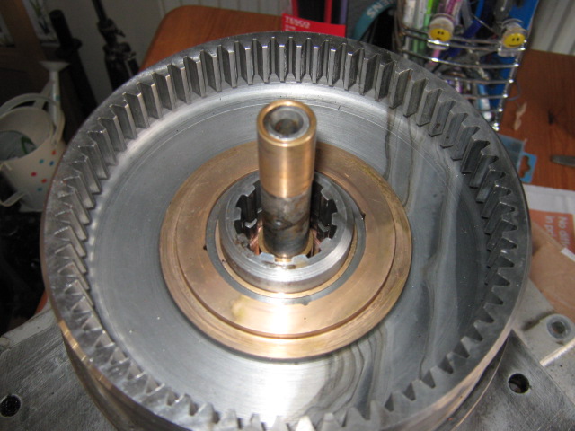
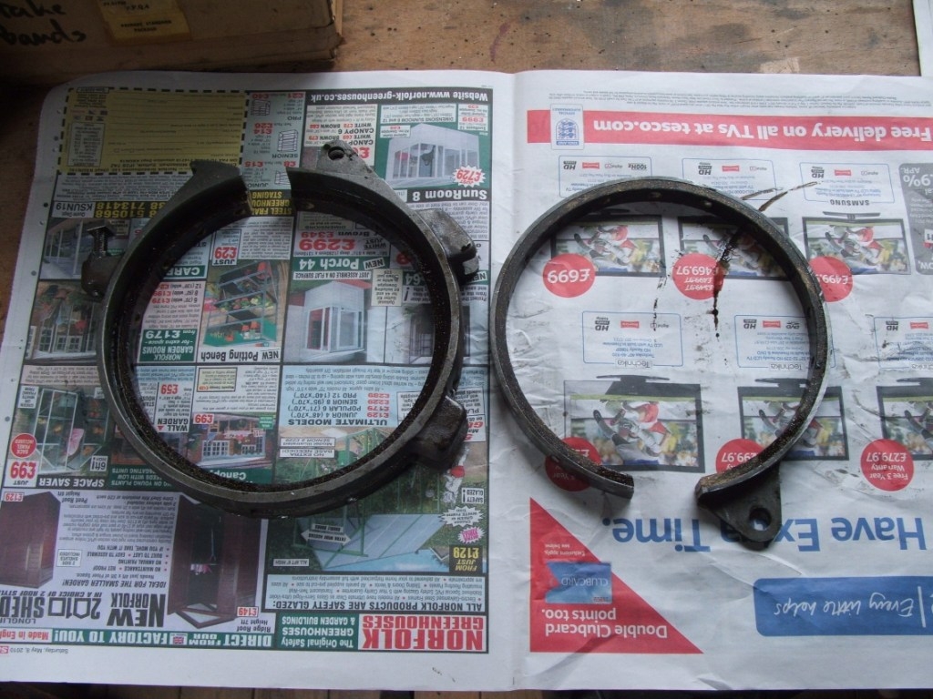
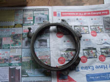
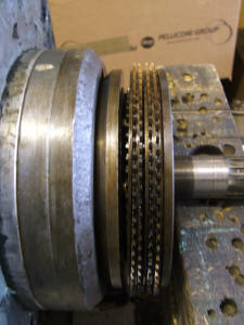
Here is the reason why new bands were required... 2nd Gear has worn out.
A few more tips we learnt when stripping the box down are below.
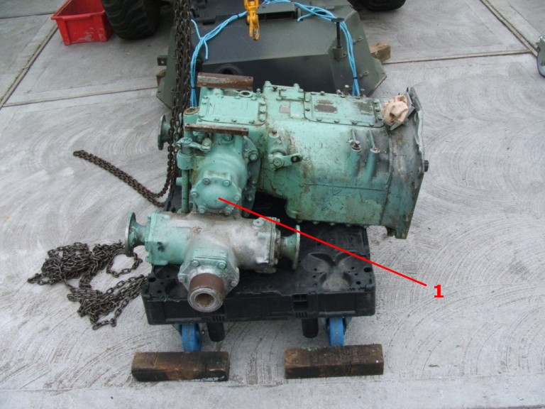
Do lift up the engine/gearbox and pack the front engine steady's before removing the box. It makes little difference getting the box out, but makes it easy to line up the input shaft into the fluid coupling splines when replacing it as the box is suspended and easy to manoeuvre.
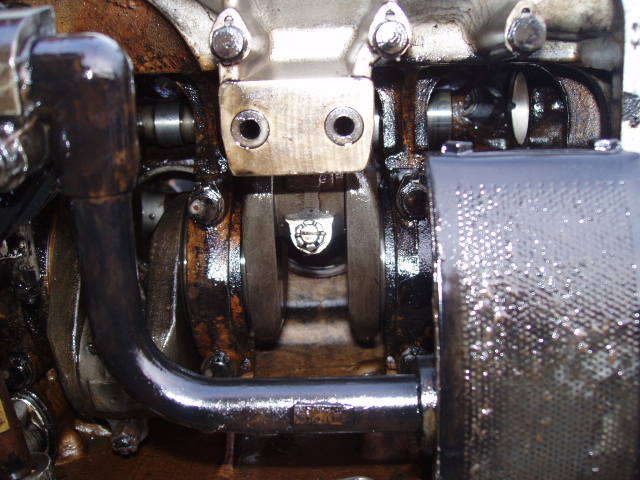
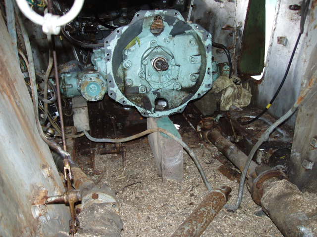
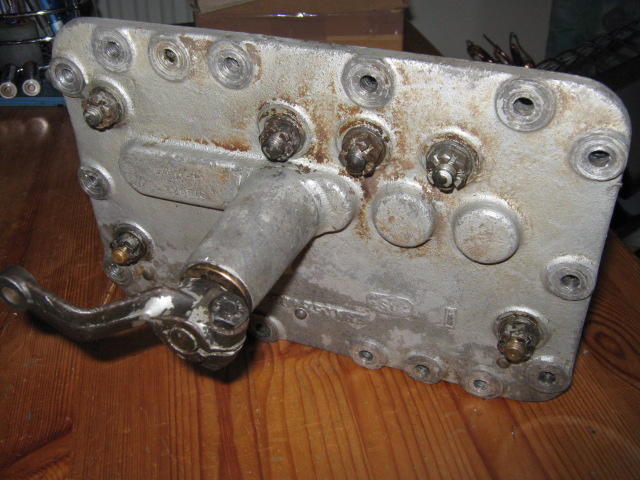
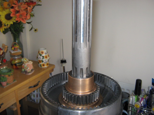
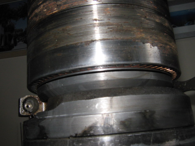
If you undo the six bolts on the small cover plate (No.1) in the picture below the input shaft from the gearbox can be rotated to allow the gearbox to mate to the fluid flywheel splines more easily.
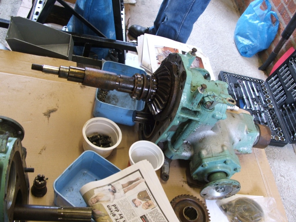
When removing the differential sides, beware the upper roller bearing, the rollers may be loose in the cage and some can drop. If you are just doing the brake bands, there is no need to split the dif, doing this just makes the box lighter to manoeuvre.
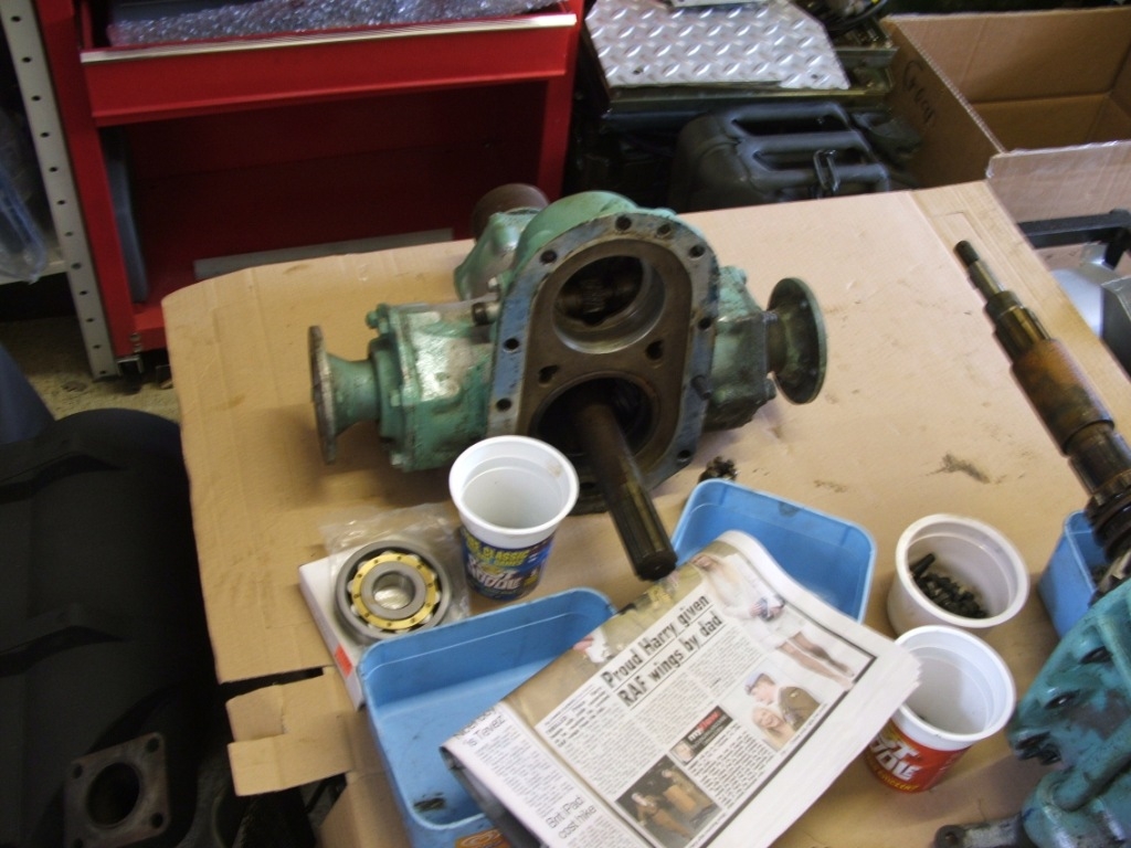
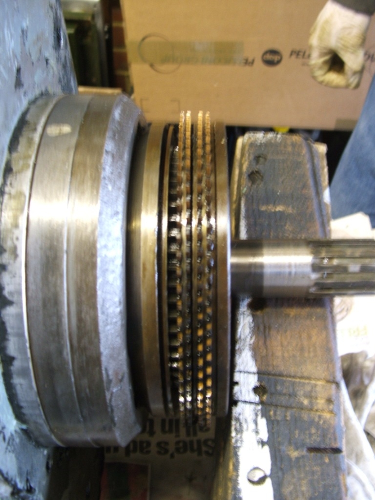
When lifting the up-ended box off the gear set, the manual says all the gears will slide out except 1st gear. This is not necessarily so, sometimes 2nd stays behind as well. If this happens, the small brass bush on the end of the engine driven shaft will drop off (picture below). With the oil sludge in the box, you may not hear it drop so beware.
Also the 5th Gear Push rod can easily drop as the box is lifted off the gear set, (ours did) same problem if you don't hear it. It's also tricky to re-fit. We waited until re-building the box, then used artery forceps to hold it in place while pulling the 5th gear pull rod up to hold it in place.
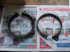
The brake band linings don't come pre-drilled, they are plain with a set of aluminium rivets (and oversize). So having drilled out the old rivets, the new band must be fitted into the band and new rivet holes drilled out, then counter bored to accept the rivet head (think asbestos at this point). Make sure the lining is absolutely flush and square in the band (use small clamps/blocks to hold it). We drilled the rivet holes through the band / lining while supporting the band / lining on a block of wood in a vice. Then removed the lining and used an 90deg angle drill to drill the counter bores to set the rivet heads down into the lining.
The manual then say's the linings mush be machined to size, using a locally made jig. They will probably need some material removed so the 1st gear will pass through. We clamped the assembled pair of bands between two sheets of 12mm mdf, one with a hole cut just smaller then the brake band internal diameter and then used a router to skim the surface until it just passed over the gear set (think asbestos at this point).
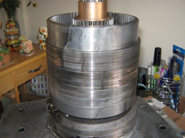
Re-assembly was just a matter of working backwards, but beware 5th gear, the plate nearest the clutch ring can slip off the inner teeth and drop. This jams the clutch so 5th gear doesn't lock (see the pictures below).
It may also stop the gear set and front housing from fully seating in the main casing. If after lowering the main box onto the gear set , there is a 2mm gap between the main casing and front housing, check the last plate.
After that. setting up the box is just a matter of following the manual, suggest getting a mate to operate the busbar lever (use a 4ft tube - beware the kick if the bar goes over centre, hang on to the tube!!!).
Also before connecting the gear selector lever to the operating rod (from the drivers gear lever), set the box to 1st gear, then the drivers lever to 1st gear, if the clevis pin won't line up, adjust the rod end. The do the same for top gear and check again. If the clevis pin doesn't line up again, set the rod half way between the point for 1st gear and 5th - this evens out the play. It still may take a few goes to get it set right.
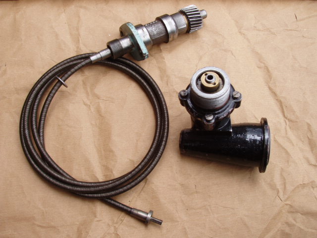
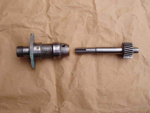
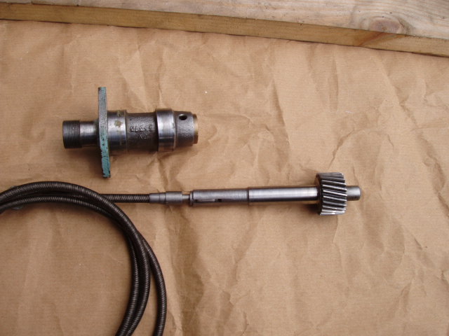
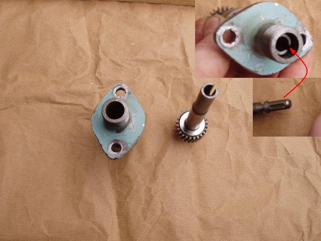
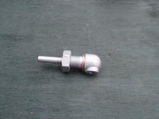
Speedo Cable (Inner Cable, Speedo & Gearbox connections)
Speedo cable length (inner) is 5ft and the Tacho cable length (inner) is 11ft. 1958 Illustrated Spare parts list page L47 or L48
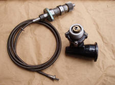

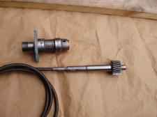
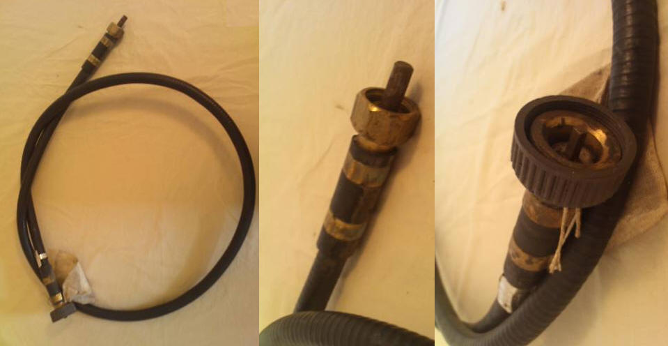
Complete Speedo Cable
Capacities Key Imperial Metric (litres) Oil Specs Military Oil Specs Civilian Steering bevel box (upper) 1 1½ pints 0.85 OEP-220 90EP Gear oil Steering cross-shaft bevel box (lower) 1 1½ pints 0.85 OEP-220 90EP Gear oil Inner tracta joint housings, including bevel boxes 2 + 10 3 pints 1.7 OEP-220 90EP Gear oil Outer tracta joint housings, including road wheel hubs 3 + 11 1½ pints 0.85 OEP-220 90EP Gear oil Front and Rear Prop shafts 4 Three grease nipples per shaft Multi purpose grease Transfer box 5 6 pints 3.41 OEP-220 90EP Gear oil Gearbox 6 1¼ gal 5.7 OMD-110 SAE 30 straight Air cleaner 7 4 pints 2.28 OMD-110 SAE 30 straight Fluid coupling 8 9¾ pints 5.52 0M13 ISO10 or ISO15 Engine lubrication system (dry sump) 9 + 12 3 gal 13.64 OMD-110 SAE 30 straight Engine cooling system 13 4½ gal 20.46 Not spec. Antifreeze Fuel Tank - total including 3 gal reserve not in pic blw 21 gal 95.5 N/A N/A Brake fluid supply tank not in pic blw 1¼ pints 0.71 OF-20 or OF-24 Dot 3 / 4
Last updated on the 16/02/2015 23:44 Copyright © 2007 - 2015